NRI—Fault finding
284 NGT Transceiver System Technical Service Manual
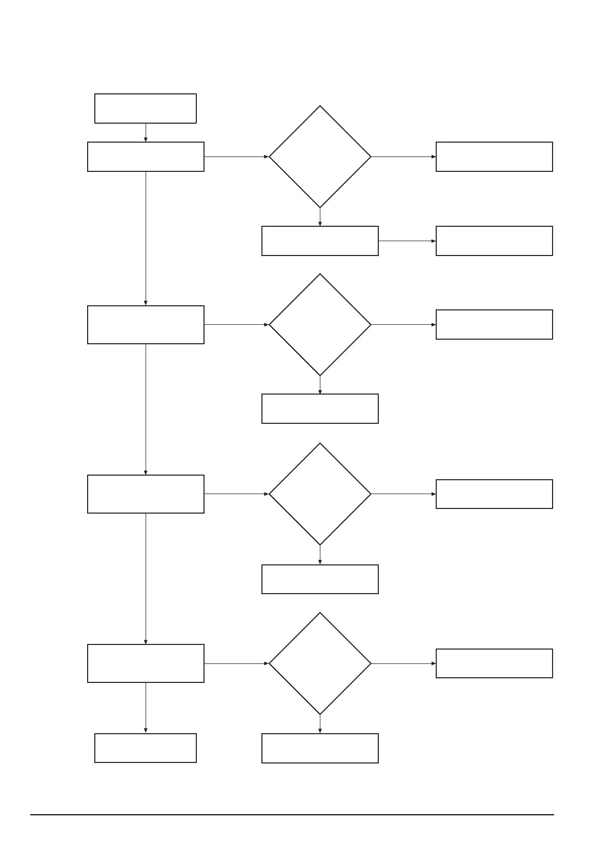
Figure 10a: NGT remote interface User Connect PCB fault diagnosis chart
NRI User Connect PCB
fault diagnosis chart
Test the overvoltage/polarity
protection circuitry by
measuring TP101.
Test the +6 V standby power
supply to the CIB by measuring
the voltage between the GND
and +6 V test points.
Test the onboard +5 V supply
rail by measuring the voltage
between the ground and
+5 V test points.
Test the serial port transmitters
by measuring the voltage
of P108 pins 3, 4 and 7 and
P109 pin 14.
Continued next page...
Is the
voltage between
+10.5 and +15 V?
Power supply or overvoltage/
polarity protection may need
repair.
Is the
voltage
+6.0 V ±0.2 V?
The +6 V standby power
supply may need repair or
refer to Codan.
Is the
voltage
+5.0 V ±0.1 V?
The onboard +5 V supply
rail may need repair or
refer to Codan.
Is the
voltage
7.5 V ±1 V?
The serial port transmitters
may need repair or
refer to Codan.
Check the power supply using
the diagnosis chart or refer
to Codan.
The overvoltage/polarity
protection is adequate.
The +6 V standby power
supply is adequate.
The onboard +5 V supply
rail is adequate.
The serial port transmitters
are operating correctly.
Yes
No
Yes
No
Yes
No
Yes
No