NGT—Overview and specifications
NGT Transceiver System Technical Service Manual 49
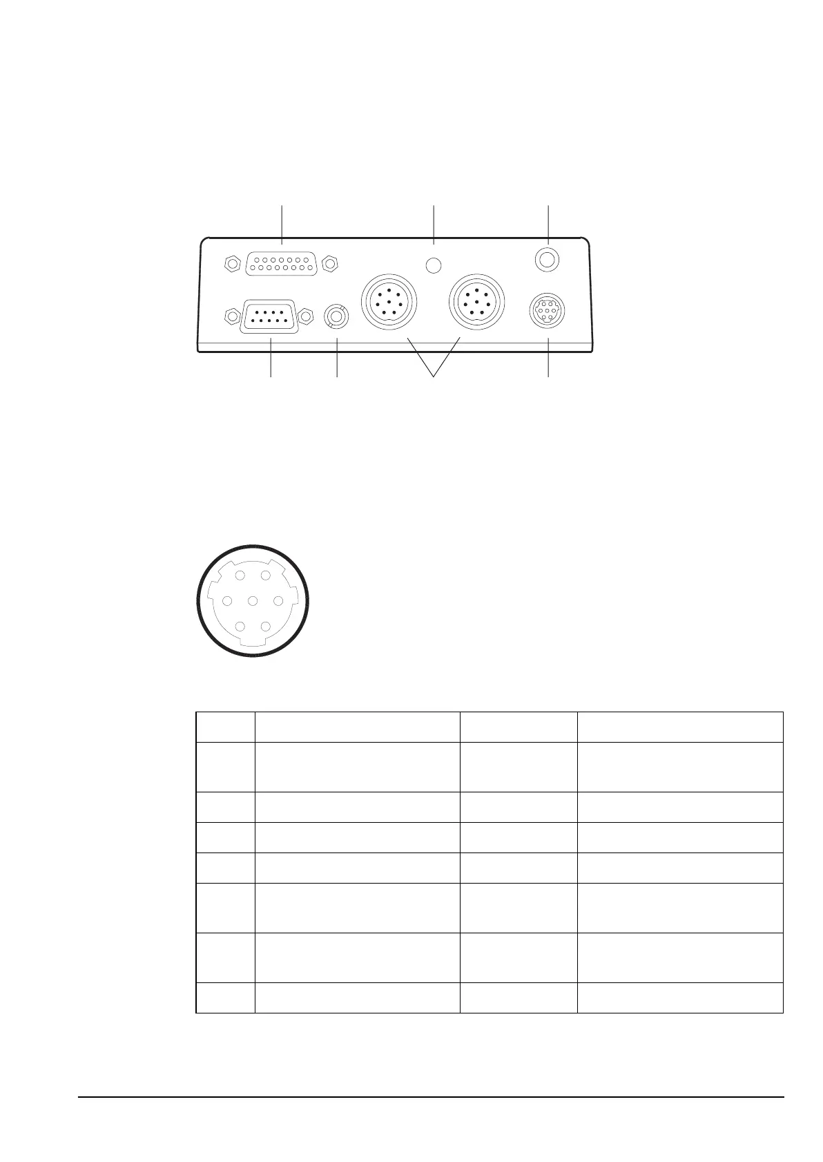
Junction box (used with 2010 RF Units only)
Figure 14: Connector panel of the junction box
Pinouts of the handset connector on the junction box
Figure 15: Front view of the handset connector on the junction box
Table 12: Pinouts of the handset connector on the junction box
Pin no. Function Input/output Signal level
1 Standby power for handset Output +5 V standby power, or
+9 V handset power
2 Handset data Input/output 1 to 5 V logic
3 Handset data Input/output 1 to 5 V logic
4 Ground 0 V
5 Microphone audio Input Nominally 500 mV p–p to
ground with normal speech
6 Microphone audio Input Nominally 500 mV p–p to
ground with normal speech
7 Power on Input Momentary 0 V = PWR ON
15-way port status light earth point
handsetCIBspeaker9-way port
1
2
3
4
5
6
7