NGT—Overview and specifications
50 NGT Transceiver System Technical Service Manual
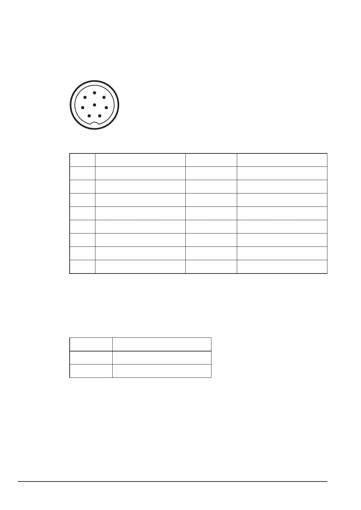
Pinouts of the CIB connectors on the junction box
Figure 16: Front view of a CIB connector on the junction box
Pinouts of the speaker connector on the junction box
The speaker should be 4 Ω with a power rating of 5 W.
Table 13: Pinouts of the CIB connectors on the junction box
Pin no. Function Input/output Signal level
1 Ground 0 V
2 System data Input/output 1 to 5 V logic
3 System data Input/output 1 to 5 V logic
4 Power on Input Momentary 0 V = PWR ON
5 +6 V standby Output +6 V
6 System audio + Input/output 5 to 10 V sync and TDM
7 System audio – Input/output 0 to 5 V sync and TDM
8 A rail protected (2 A) Output +13.6 V nominal
Table 14: Pinouts of the speaker connector on the junction box
Connection Function
Tip Speaker audio output
Sleeve Ground
1
2
3
4
5
6
7
8