NRI—Fault finding
NGT Transceiver System Technical Service Manual 277
Test procedures
It is recommended that the NRI be tested in the following order:
• the switchmode power supply where applicable
• the NRI as a stand-alone unit
• the NRI Microcontroller PCB
• the NRI Vocoder PCB
• the NRI User Connect PCB
Testing the switchmode power supply
To test the switchmode power supply:
1 Connect the switchmode power supply to a mains supply and switch it on.
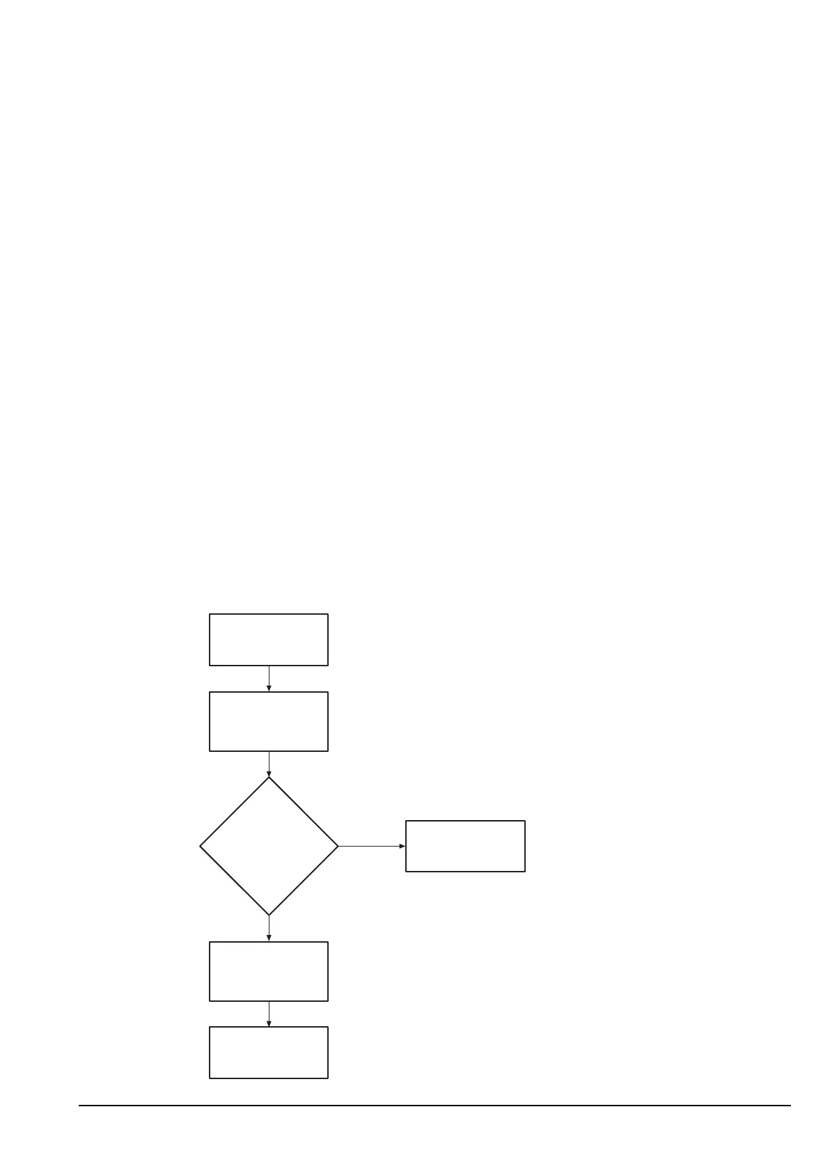
1 Follow the steps in Figure 8 to assist in fault finding.
Figure 8: Power supply fault diagnosis chart
CAUTION
To avoid port failure, field service technicians using the Test connector of
the NRI during NRI testing or debugging should run laptops from the
internal battery instead of using the mains supply.
Is voltage
+13.5 V?
(10.5 to 15 V
is allowable)
No
Yes
Fault find the NRI
User Connect
PCB.
Measure the voltage
terminals of the power
supply present at the
output.
Power supply fault
diagnosis chart
Power supply may
need replacement
or repair.
Refer to Codan.