Introduction P/N 709C011801 Page 18
Table 1-6. Digital Path Remote End Power Specifications
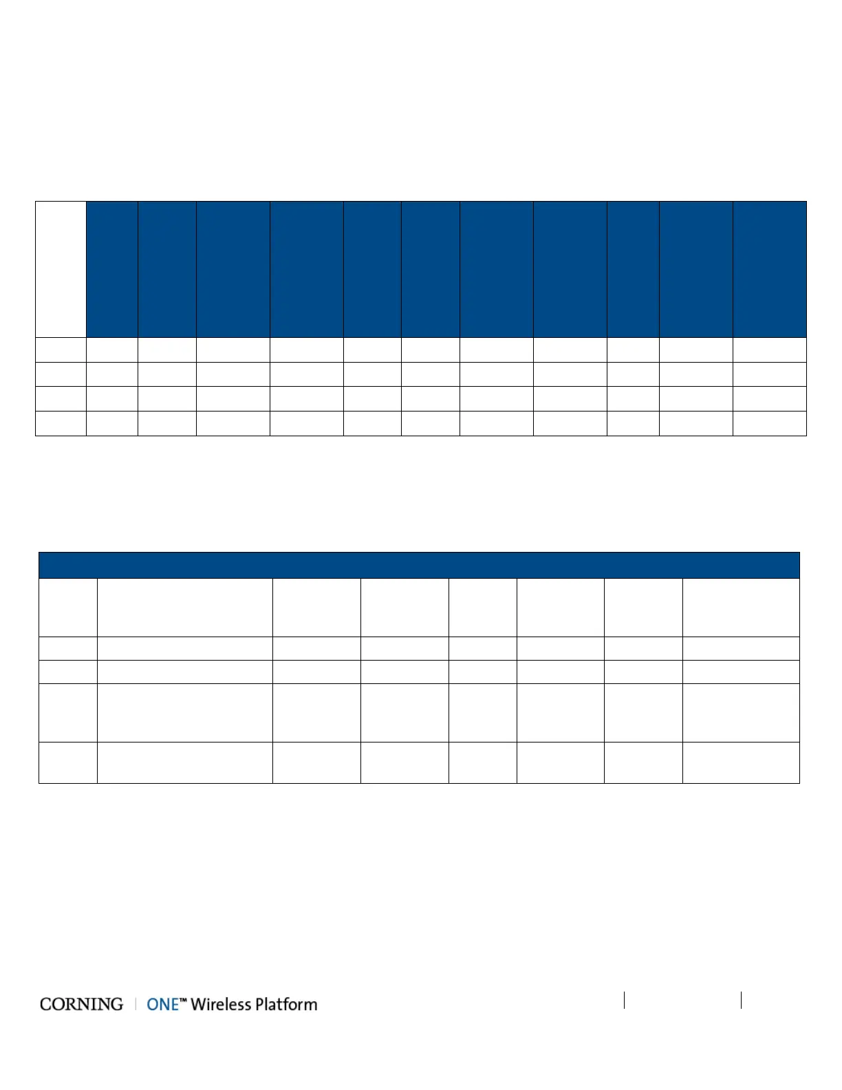
1.3.3.2 Cable Gauge Requirements
Table 1-7 provides the information required to calculate the required power supply for the remote units.
SISO
(ft)
+
GEM
(ft)
+
GEM
Supporting
PoE
+
GEM
Supporting
PoE+
(ft)
MIMO
(ft)
MIMO
+
GEM
(no
PoE)
(ft)
MIMO
+
GEM
Supporting
PoE
(ft)
MIMO
+
GEM
PoE+
(ft)
(ft)
Supporting
PoE
(ft)
Supporting
PoE+
(ft)
22AWG 540 490 410 100 310 290 290 100 2000 310 80
20AWG 870 780 650 160 500 460 460 160 3200 500 130
16AWG 2200 1900 1600 400 1200 1100 1100 400 8200 1200 350
14AWG 3500 3100 2650 650 2010 1800 1800 650 1350 2000 550
Table 1-7. Required Cable Gauge
1.3.3.3 Power, Heat and Rack Specifications
Table 1-8 and Table 1-9 provide the power, heat and rack specifications for the headend and remote end ceiling equipment.
Headend/Telco Rms
HEU Headend Unit 100 -220 200 1 680 4 7 x 17.3 x 18.9
OIU Optical Interface Unit 100 - 220 300 1 1020 4 7 x 17.3 x 18.9
CEU
Centralized Ethernet Unit
(3 x CEMs – Centralized
Ethernet Modules)
110 - 240 50 1 170 1 1.75 x 17 x 8.5
ICU
Intermediate Centralized
Unit (4 x 200 W PSMs)
110 - 240 930 1 442 1 1.75 x 17 x 19.2
Table 1-8. Power, Heat and Rack Specifications for Headend Equipment