Installation – RF Path Elements P/N 709C011801 Page 76
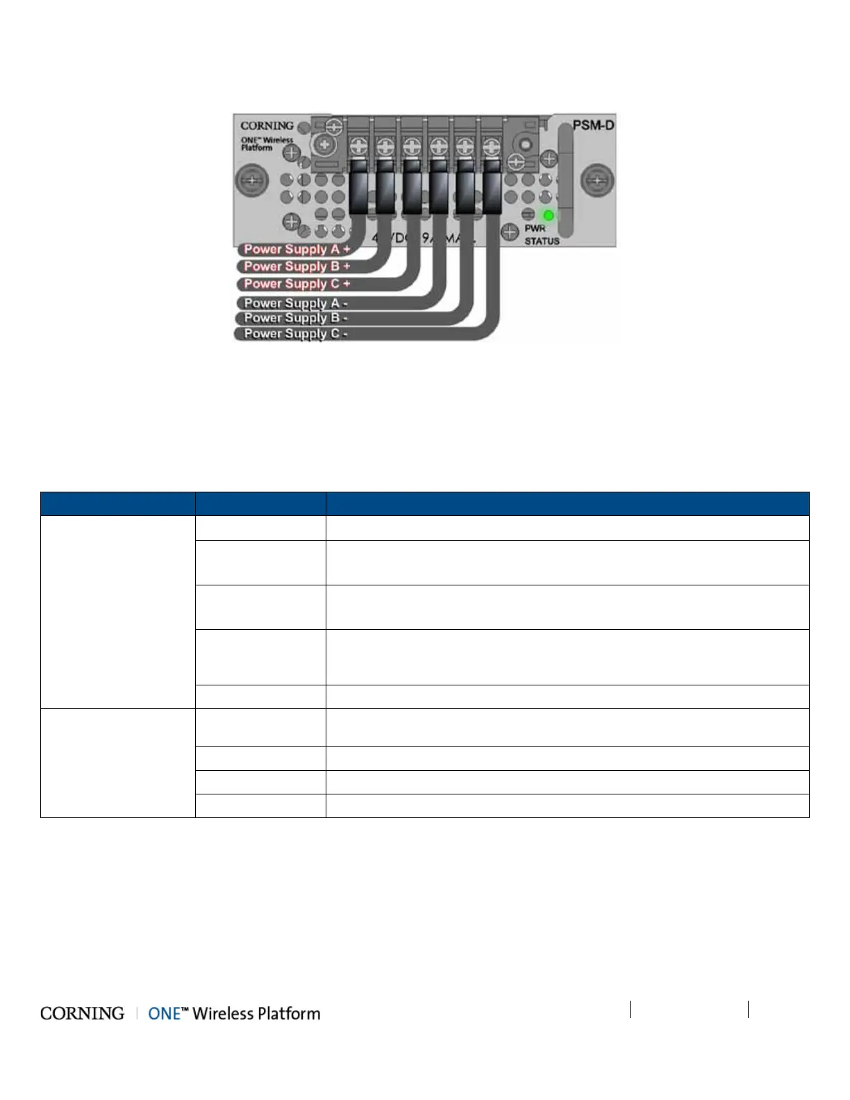
3. Turn on DC source and verify that power status LED is green.
Figure 5-21. Connected DC Wire Pairs and Green Power LED
5.1.2.11 Verify Normal operation
1. Verify that the Power Status LED on each PSM shows green. See Figure 5-18 (PSM-AC) and Figure 5-21 (PSM-DC).
2. If RF source is operational, verify that the RIM (see Figure 5-22) and HCM/ACM (see Figure 5-23) LEDs indicate normal
operation according to Table 5-6:
Module LED Description
RIM Protect N/A
DL High Off - DL RF input level in threshold range
Steady Red – DL RF input level is 3dB above max expected power
DL Low Off - DL RF input level in threshold range
Steady Red - DL RF input level is 15dB below max expected power
RUN Blinking Green - RIM module SW has initialized and is up and running
Off – Power off
PWR Steady green - Input power is within required range
HCM/ACM PWR Steady Green - Power input detected by HCM/ACM
RUN Blinking Green – HCM module SW up and running
SYS Steady Green - Overall status of the managed system is ok
FAN Steady Green – Normal operation status for all fans
Table 5-6. RIM and HCM/ACM LED Descriptions