Installation – RF Path Elements P/N 709C011801 Page 96
5. Connect the DC wiring and fibers from the opposite end of the composite cable to the RAU/GEU units - described in
corresponding QSG documents.
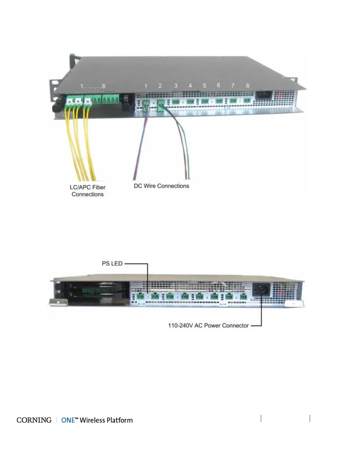
Figure 5-48. ICU Fiber and DC Connectors
5.2.1.8 Power Up
1. Connect the ICU power connector (front panel) to the AC power outlet using the provided power cable.
2. Verify that the PS LED indicators (located between the corresponding DC connectors on the front panel) show green. Refer
to Figure 5-49.
Figure 5-49. AC Power Connection and LEDs