Installation – RF Path Elements P/N 709C011801 Page 71
5.1.2.8 RIX Pilot Clock Connections
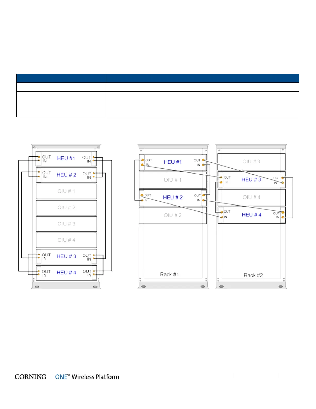
Referring to Figure 5-14 (Shared Rack), use the QMA/QMA jumper cable to connect the REF OUT and REF IN ports of each of
the RIX modules in the HEU chassis.
Note that The REF IN and REF OUT pilot clock ports must be connected in a closed loop as shown in Figure 5-14 and
Figure 5-15 and that both RIX modules of each chassis must be connected.
From To
Main HEU RIX
1
Auxiliary HEU RIX
(For additional Auxiliary HEUs)
1
st
Auxiliary HEU RIX
2
nd
Auxiliary HEU RIX
2
Auxiliary HEU RIX
Auxiliary HEU RIX
Table 5-3.IX Pilot Clock Connections
Figure 5-14 and Figure 5-15 show an example of the required pilot clock connections in 4x4 configurations.
Figure 5-14. Pilot Clock Connections Diagram
– (4x4) Shared Rack
Figure 5-15 Pilot Clock Connections Diagram – (4x4) Dedicated Rack