Installation – RF Path Elements P/N 709C011801 Page 95
5.2.1.5 Mounting ICU on Wall
1. Remove the rack mounting brackets and set the screws aside.
2. Using the screws (previously set aside), assemble the wall mount brackets onto the sides of the ICU.
3. Using the wall mount bracket holes as a guide, mark the holes to be drilled on the wall.
5.2.1.6 Connect MTP Fiber
Note: The fiber connection is performed between the Edge module MTP connector and the FMU (Fiber Management Unit)
using a trunk cable.
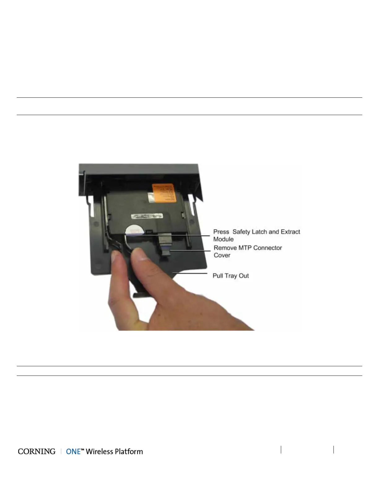
4. From the rear panel, pull the tray with the Edge module all the way out.
5. Gently extract the edge module by pressing on the safety latch and pulling slowly outwards. Refer to Figure 5-47.
6. Remove the MTP connector cover and connect the MTP fiber cable.
7. Push in the module tray.
Figure 5-47. Extracting Edge Module
5.2.1.7 Composite Cable Connections
Note: The composite cable connections are connected towards the RAU and/or GEU units.
1. Connect one side of the composite cable DC wiring to any of the ICU DC power connectors (1-8) on the front panel. See
Figure 5-48.
2. Extract the Edge module (see Steps 1-4 of 5.2.1.6), remove the tip covers from the composite cable fiber pairs and
connect to the Edge module LC/APC fiber connectors. See Figure 5-48.
3. Note the cable coding on the fibers.
4. Push Edge module and tray back in place.