Installation – RF Path Elements P/N 709C011801 Page 81
5.1.3.3 Installing All Modules
Note: For modules with ejectors (i.e. OIM, OIX and ACM) – verify that the ejectors are completely open when inserting in
dedicated slot and then push in until the module clicks in to the backplane. Figure 5-28 shows example of module type
captive screws and ejectors.
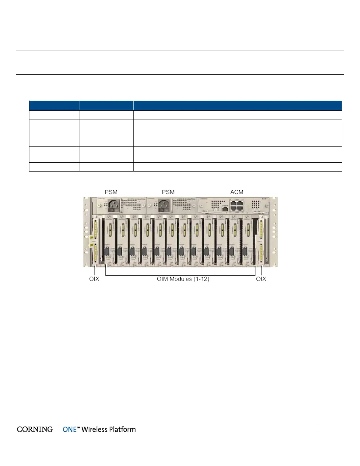
1. Refer to Figure 5-27 for module locations. Remove blank panel (where relevant) and slide in the relevant module (chassis
slots are 100% mistake proof):
ACM 1 -
PSM 1 - 2
• For installations with one PSM module – install module in left most slot
• For installations with two PSM modules – remove blank panel from middle
slot and insert additional PSM module
OIX 1 - 2
For single OIX installations, the second OIX slot must be occupied with an
Expander Termination Module (ETM).
OIM 1 - 12 No need to terminate unoccupied OIM slot – leave blank panel
Figure 5-27. Location of OIU Front Panel Modules in Chassis
2. Secure modules into the OIU backplane by:
• Closing ejectors firmly (for relevant modules)
• Tightening the captive screws
See Figure 5-28.