Unit Descriptions - RF Path P/N 709C011801 Page 45
2.3.1 ICU (Intermediate Centralized Unit)
Note: The ICU unit is common for the RF and Digital path components.
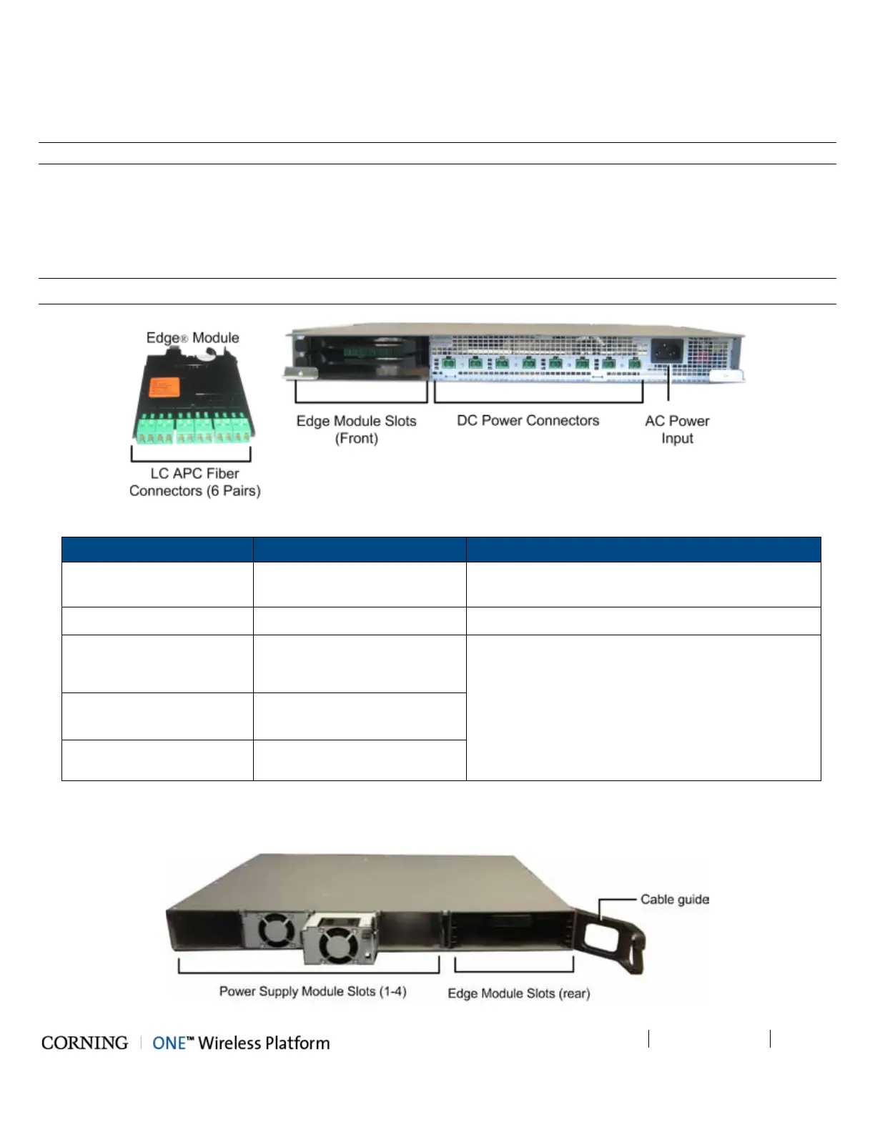
The ICU is installed at the floor level. It provides the LC APC optical interface along with DC power to the RAU RF (and data)
sub-modules. The optical and DC signals are routed via a composite cable connected between the ICU and hosted RAU
modules. The optics signal is provided via one or two dedicated Edge
®
modules that convert MTP optic interfaces to LC/APC
interface; the DC power is provided by up to four dedicated power supplies. A single power connection feeds all ICU power
supply modules.
Note: Pretium EDGE
®
Module – MTP
®
to LC APC splice module/cassette/field-term cassette
Figure 2-13. ICU Front Panel Interfaces and Modules
Chassis/Module Interface Description
ICU Chassis Power Connectors Up to eight DC power connectors, depending on
number of power supply modules installed.
PSM AC Power Input 110-240 V AC power input to unit
Edge
®
Module
LC APC SM
Optic connectors implemented by up to two Edge
®
modules inserted from the rear: six connectors per
Edge
®
module.
MTP
®
SM fiber port
Edge
®
Splice Cassette
LC APC to a (twelve x 250µm
single fiber) pigtail
Edge
®
Field-Term Cassette
LC APC to LC APC
Table 2-11. ICU Front Panel Interface Descriptions
Edge
®
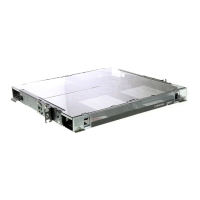
modules and power supplies are extracted and inserted from the rear of the unit.
Figure 2-14. ICU Rear Panel Interfaces and PSM Modules