Installation – RF Path Elements P/N 709C011801 Page 88
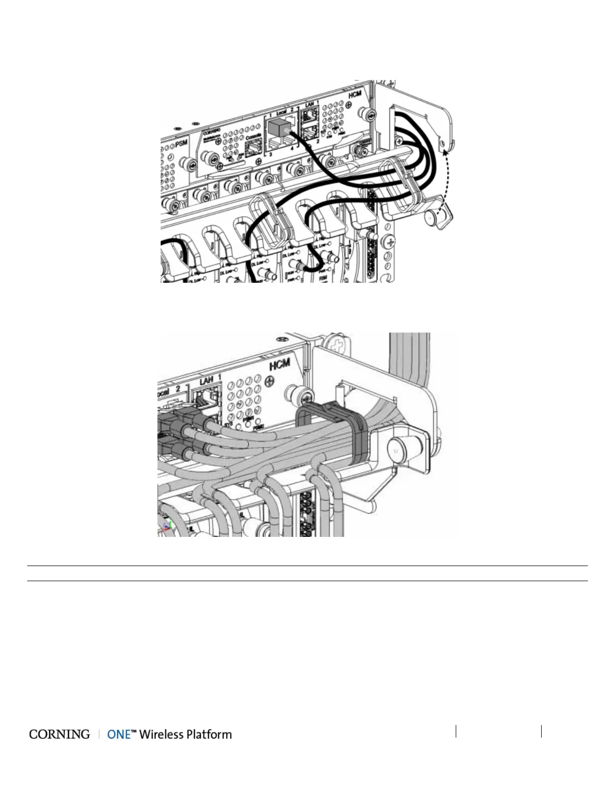
2. Route Connection Cables Through Cable Tray (From the Middle Leftwards/Rightwards) and Pull Up Tray
Figure 5-36. Assembling Cable Tray
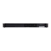
3. Close Management Tray (as shown in figure)
Figure 5-37. Assembling Cable Tray
Note: The tray pin must first be pulled towards the left and then released into the hole (shown in figure above).