xStack® DGS-3120 Series Layer 3 Managed Gigabit Ethernet Switch Web UI Reference Guide
206
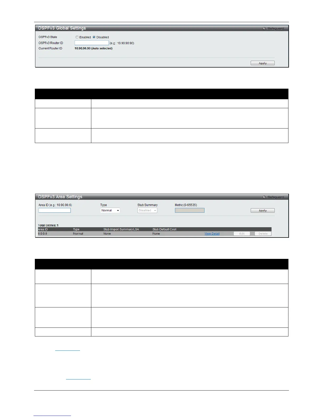
Figure 5-58 OSPFv3 Global Settings window
The fields that can be configured or displayed are described below:
Parameter Description
Click the radio buttons to enable or disable the OSPFv3 global state.
OSPFv3 Router ID
Enter a 32-bit number in the form of an IPv4 address that uniquely identifies the router
in the OSPFv3 domain. Setting it to be 0.0.0.0 means auto-selected. The Switch will
select the largest IPv4 address among the IP interfaces to be the router ID.
Current Router ID
Display the OSPFv3 Route ID currently in use by the Switch. This Route ID is
displayed as a convenience to the user when changing the Switch’s OSPFv3 Route ID.
Click the Apply button to accept the changes made.
OSPFv3 Area Settings
This window is used to configure the OSPFv3 area settings for the Switch.
To view the following window, click L3 Features > OSPF > OSPFv3 > OSPFv3 Area Settings, as shown below:
Figure 5-59 OSPFv3 Area Settings window
The fields that can be configured are described below:
Parameter Description
Area ID
Enter the OSPFv3 area’s ID. It is a 32-bit number in the form of an IPv4 address that
uniquely identifies the OSPFv3 area in the OSPFv3 domain.
Type
Specifies the OSPFv3 area mode of operation.
Normal – The OSPFv3 area will be created as a normal area.
Stub – The OSPFv3 area will be created as a stub area.
Stub Summary When Stub is selected in the Type drop-down menu, use the drop-down menu to
specify whether the OSPFv3 stub area imports inter-area prefix LSA advertisements or
Enter the default cost of OSPFv3 stub area.
Click the Apply button to accept the changes made.
Click the View Detail link to view a display of OSPFv3 Area Settings.
Click the Edit button to re-configure the selected entry.
Click the Delete button to remove the selected entry.
After click the View Detail link, the following window will appear.

 Loading...


