FC 300 Design Guide
How to Program
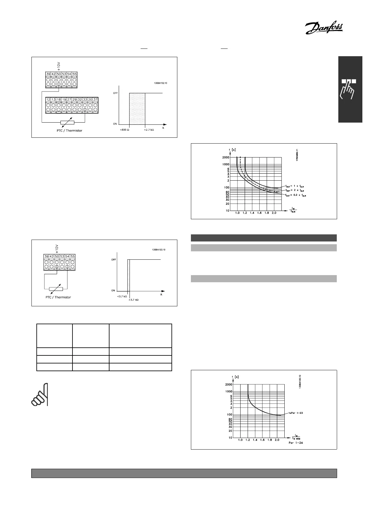
Using an analog input and 10 V as power supply:
Example: The frequency c o nverter t rips when
the m otor temperature is too high.
Parameter set-up:
Set Par. 1-90 Motor Thermal Protection
to Thermistor Trip [2 ]
Set Par. 1-93 Thermistor Source to
Analog Input 54 [2]
Do not select a reference source.
Input
Digital/ana-
log
Supply
Voltage
Volt
Threshold
Cut-out Values
Digital 24 V <6.6kΩ - > 10.8 kΩ
Digital 10 V < 800Ω ->2.7kΩ
Analog 10 V <3.0kΩ ->3.0kΩ
NOTE
Che
ck that the chosen sup ply voltage
follows the speci fication of the used
thermistor element.
Se
lect ETR Warning 1-4, to activate a warning on
the display when the m otor is overloaded.
Select ETR Trip 1-4 to trip the frequency converter
w
hen the motor is overloaded.
Programme a warning signal via one of the
digital outputs. The signal appears in the event
of a warning and if the frequency converter
trips (thermal warning).
ETR (Electronic Terminal Relay) functions 1-4 w ill
calculate the load when the set-up where they were
selected is active. For example ETR starts calculating
when setup 3 is selected. For the No r th American
market: The ETR functions provide class 20 motor
overload p rotection in accordance with NEC.
1-91 Motor External Fan
Option:
*
No [0]
Yes [1]
Function:
Select No [0] if no external fan is required, i.e.
the motor is derated at low speed.
Select Yes [1] to apply an external motor fan
(external ventilation), so no derating of the motor is
required at low speed. T he graph below is followed
if the motor current is lower than nominal motor
current (see par. 1-24). If the motor current
exceeds nom inal current, the ope ration time still
decreases as if no fan were installed.
*
default setting ()display text []value for use in communication via serial communication port
171
MG.33.B
6.22 - V LT is a registered Danfoss trademark

 Loading...


