FC 300 Design Guide
How to Program
Thermistor warning [1]
Thermistor trip [2]
ETR warning 1 [3]
ETR trip 1 [4]
ETR warning 2 [5]
ETR trip 2 [6]
ETR warning 3 [7]
ETR trip 3 [8]
ETR warning 4 [9]
ETR trip 4 [10]
Function:
The frequency converter determines the
motor temperature formotor protection in
two different ways:
• Via a thermistor sensor connected to
one of the ana log or digital inputs (par.
1-93 Thermistor Source).
• Via calculation (ETR = Electronic Terminal
Relay) of the thermal load, based on the actual
load and time. The calculated thermal load
is com pare d with the rated motor current
I
M,N
and the rated motor frequency f
M,N
.The
calculations estimate the need for a lower
load at lowe r speed due to less cooling from
the fan incorporated in the motor.
Select No protection [0] for a continuously
overloaded motor, when no warning or trip
of drive is required.
Select Thermistor warning [1] to activate a warning
when the connecte d thermistor in the motor reacts
in the event of motor over-temperature.
Select Thermistor trip [ 2] to stop (trip) the
frequency converter when the connected
thermistor in the motor reacts in the e
vent
of motor over-tem perature.
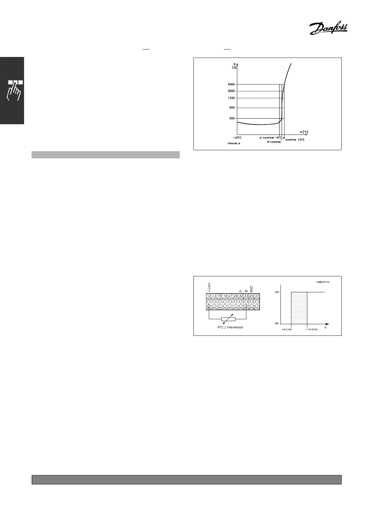
The thermistor cut-out value i s > 3 kΩ.
Integrate a thermistor (PTC sensor) in the
motor for winding protection.
Motor protection can be implemented using a range
of techniques: PTC sensor in motor windings;
mechanical thermal switch (Klixon type); or
Electronic Thermal Relay (ETR).
See parameter group 1-9* Motor Temperature.
Using a digital input and 24 V as power supply:
Example: The frequency converter trips when the
motor temperature is too high Parameter set-up:
Set Par. 1-90 Motor Therma l Protection
to Thermistor Trip [2]
Set Par. 1-93 Thermistor S o urce to Digital Input [6]
Using a digital input and 10 V as power su
pply:
Example: The frequency converter trips when
the m otor temperature is too high.
Parameter set-up:
Set Par. 1-90 Motor Therma l Protection
to Thermistor Trip [2]
Set Par. 1-93 Thermistor S o urce to Di
gital Input [6]
*
default setting ()display text []value for use in communication via serial communication port
170
MG.33.B
6.22 - V LT is a registered Danfoss trademark

 Loading...


