FC 300 Design Guide
How to Program
5-53 Term. 29 High Ref./Feedb. Value
Range:
Par. 5-52 - 1000000.000
*
1500.000
Function:
Enter the high reference value [RPM] for the motor
shaft speed and the high fe ed back value, see also
par. 5-58. Selec t te rminal 29 as a digital output (par.
5-02 = Output [1] and par. 5-13 = applicable value).
This parameter is available for the FC 302 only.
5-54 Pulse Filter Time Consta nt #29
Range:
1 - 1000 ms
*
100 ms
Function:
Enter the pulse filter time constant. The pulse
filter dampen s oscillations of the feedback signal,
which is an advantage if there is a lot of noise
in the system . A high time constant value
results in better dampening but also increases
the time delay through the filter. This parameter
is available for the FC 302 only.
This parameter cannot be adjusted while
the motor is running.
5-55 Term. 33 Low Frequency
Range:
0 - 110000 Hz
*
100Hz
Function:
Enter the low frequency corresponding to the low
motor shaft speed (i.e. low reference value) in par.
5-57. Refer to the diagram in this section.
5-56 Term. 33 H igh Frequ en cy
Range:
0 - 110000 Hz
*
100 Hz
Function:
Enter the high frequency corresponding to the
high motor shaft speed (i.e. high reference
value) in par. 5- 58.
5-57 Term. 33 Low Ref./Feedb. Va l ue
Range:
-100000.000 - pa r. 5-58)
*
0.000
Function:
Enter the low reference value [RPM] for the
motor shaft speed. This is also the low feedback
value, see also par.5-52.
5-58 Term. 33 High Ref./Feedb. Value
Range:
Par. 5-57 - 100000.000
*
1500.000
Function:
Enter the high reference value [RPM] for the
motor shaft speed. See also par. 5-53 Term.
29 High Ref./Feedb. Value.
5-59 Pulse Filter Time Constant #33
Range:
1 - 1000 ms
*
100ms
Function:
Enter the pulse filter time constant. The low-pass
filter reduces the influence on and dampens
oscillations on the feedback signal from the control.
This is an advantage, e.g. if there is a gr eat amount
on noise in the system. This parameter cannot
be adjusted while the motor is running.
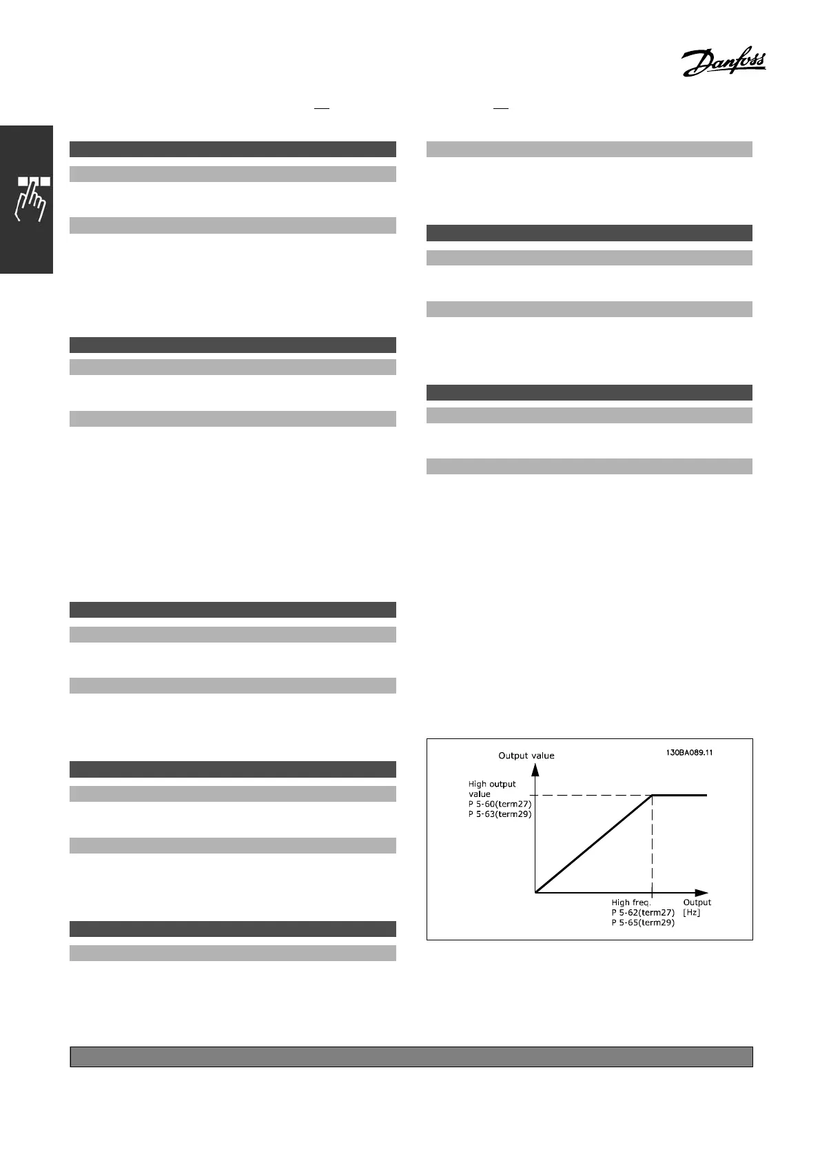
" 5-6* Pulse Outputs
Parameters for configuring the scaling and
output functions of pulse outputs. The pulse
outputs are designated to term inals 27 o r 29.
Select terminal 27 output in par. 5 -01 and
terminal 29 output in par. 5-02.
Options for readout output variables:
*
default setting ()display text []value for use in communication via serial communication port
198
MG.33.B
6.22 - V LT is a registered Danfoss trademark

 Loading...


