FC 300 Design Guide
How to Program
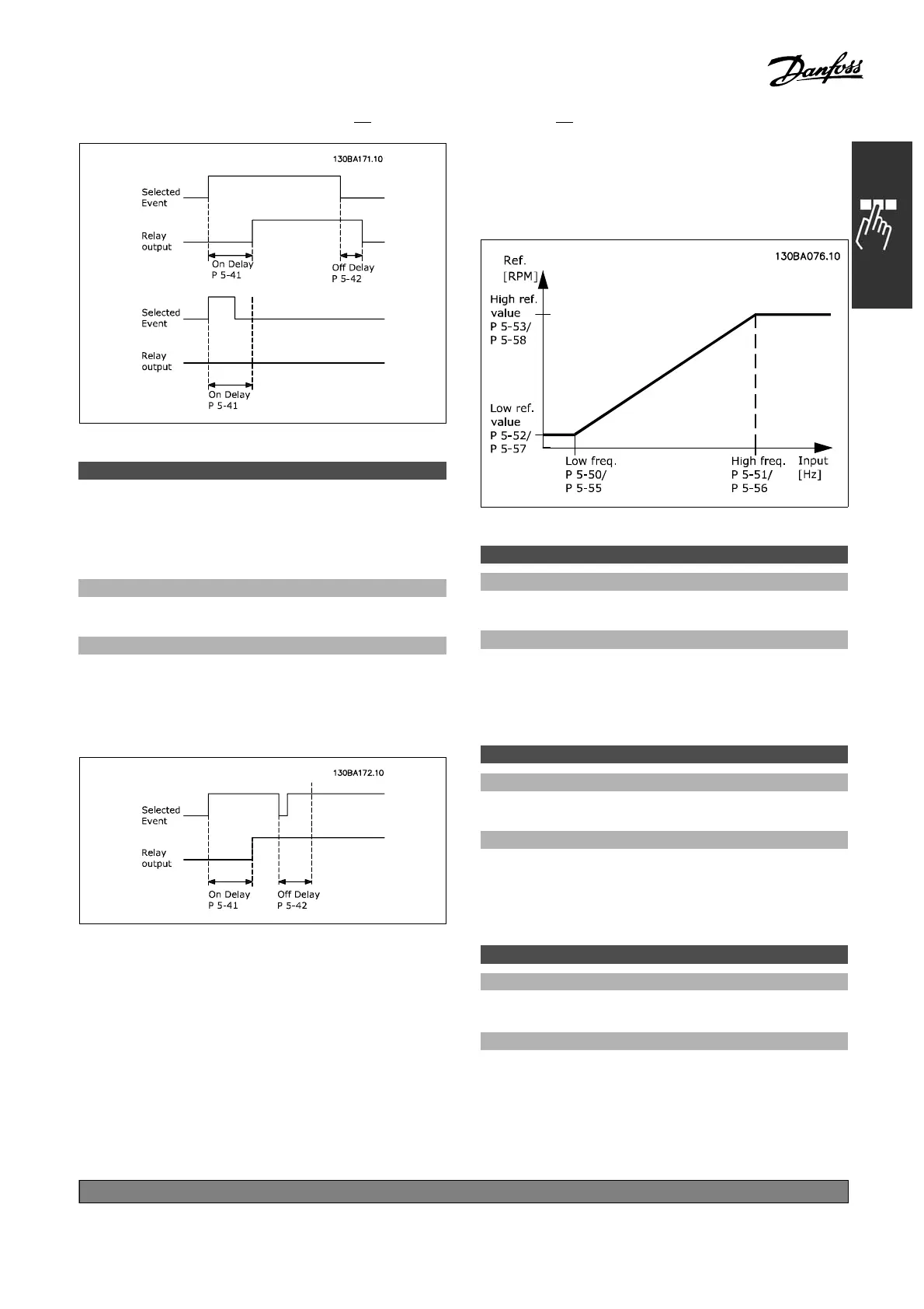
5-42 Off Delay, Relay
Array [8] (Relay 1 [0], Relay 2 [1],
Relay 7 [6], Relay 8 [7],
Relay 9 [8])
Range:
0.01 - 600.00 s.
*
0.01s
Funct
ion:
Enter the delay of the relay cut-out time. Select
oneofavailablemechanicalrelaysandMCO105
in a
n array function. See par. 5-40.
If the selected event condition changes
before the on or off del ay timer e x pires, the
relay output is unaffected.
" 5-5* Pu lse Input
The pulse input parameters are used to define
an appropriate window for the impulse reference
area by configuring the scaling and filter settings
for the pulse inputs. Input terminals 29 or 33
act as frequency reference inputs. Set terminal
29 (par. 5-13) or terminal 33 ( par. 5-15) to
Pulse input [32]. Ifterminal29isusedasan
input, then set par. 5-01 to Input [0].
5-50 Term. 29 Low Frequency
Range:
100 - 110000 Hz
*
100Hz
Function:
Enter the low frequency limit corresponding to the
low m otor shaft speed (i.e. low reference value) in
par. 5-52. Refer to the diagram in this section.
This parameter is available for FC 302 only.
5-51 Term. 29 High Freque nc y
Range:
0 - 110000 Hz
*
100Hz
Function:
Enter the high frequency limit corresponding
to the high m otor shaft speed (i.e. high
reference value) in par. 5-53.
This parameter is available for FC 302 only.
5-52 Term. 29 Low Ref./Feedb. Value
Range:
-1000000.0 00 - par. 5-53
*
0.000
Function:
Enter the low re f erenc e value limit for the motor
shaft speed [RPM]. This is also the lowest feedback
value, see also par. 5-57. Set term inal 29
to digital output (par. 5-02 =Output [1] and
par. 5-13 = applicable value).
This parameter is available for the FC 302 only.
*
default setting ()display text []value for use in communication via serial communication port
197
MG.33.B
6.22 - V LT is a registered Danfoss trademark

 Loading...


