Terms of Tool Position
This manual uses the following terms to indicate the position of the tool.
Terms Overview
Coordinates
These refer to the numerical values that indicate the position of the tool on each of the X/Y/Z axis. They are represented
along with the axis, and the values are represented as positive or negative numbers.
Axis Distance from the origin
XYZ 100%
S 100%
X 35.00mm
Y 23.00mm
Z 0.00mm S 5000rpm
01234567890123456 待機中
(Representation)
The following are the two types of coordinates.
• "Machine coordinates": Coordinates whose origin is a machine-specic origin (machine origin) that
cannot be changed.
• "User coordinates": Coordinates whose origin is an origin that can be changed by the user (user origin).
Origin This refers to the origin ("0" position) of coordinates.
X
Y
Z
Origin
X-axis
coordinate
This refers to the distance from the origin of the X
axis direction (horizontal direction when the table is
seen from directly above).
Y-axis
coordinate
This refers to the distance from the origin of the Y
axis direction (vertical direction when the table is
seen from directly above).
Z-axis
coordinate
This refers to the distance from the origin of the Z
axis direction (height direction).
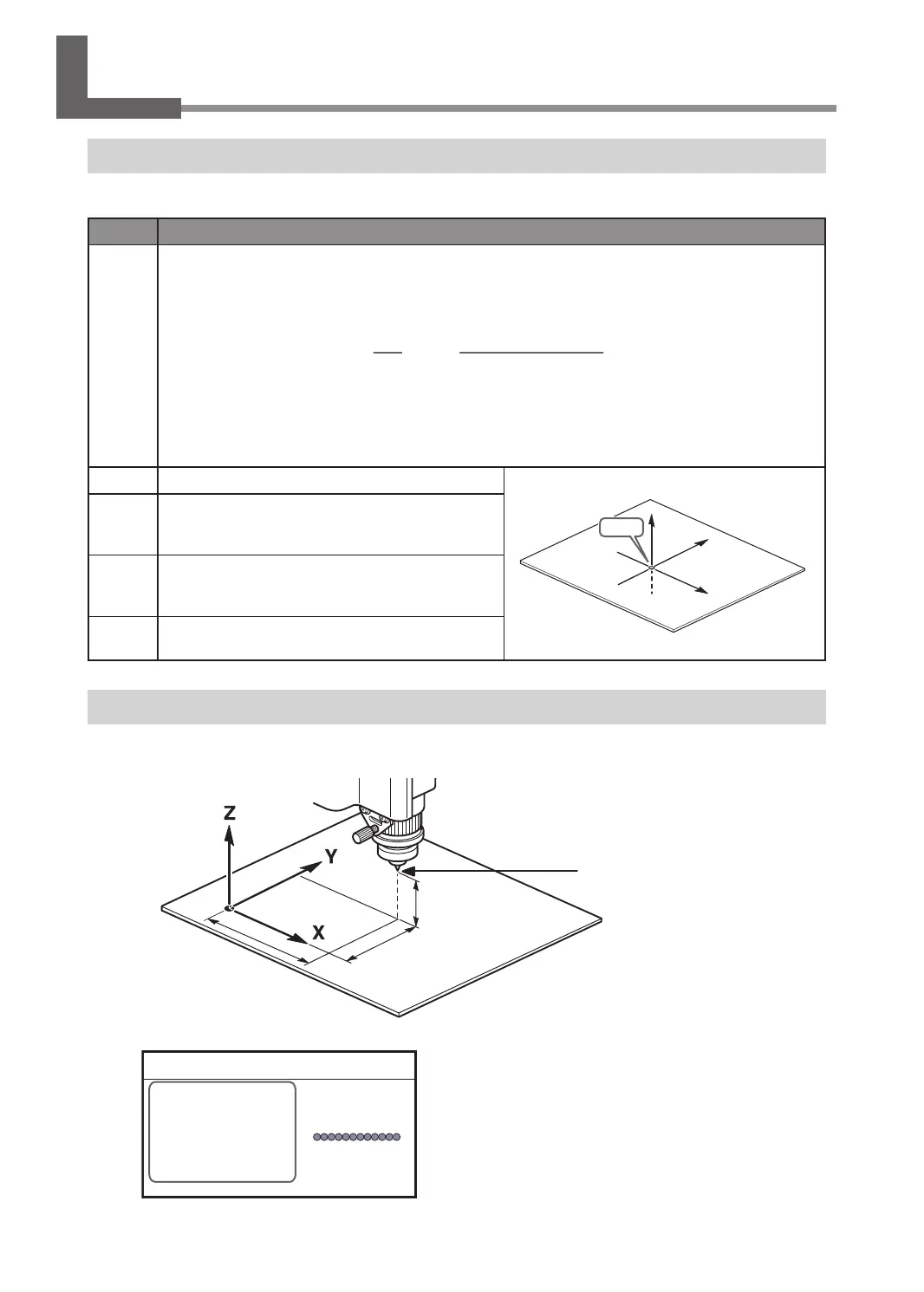
Display Example of Tool Position
¾ When the tool has moved from the origin by 50 mm (2.0 in.) along the X axis, 30 mm (1.2 in.) along the Y
axis, and 20 mm (0.8 in.) along the Z axis.
50 mm (2.0 in.)
30 mm (1.2 in.)
20 mm (0.8 in.)
Origin
Actual tool position
This tool position is displayed on the handy panel's main screen as shown below.
X 50.00mm
Y 30.00mm
Z 20.00mm S 5000rpm
012345678901234567 READY
Moving the Tool
18
Chapter 2 Basic Operation