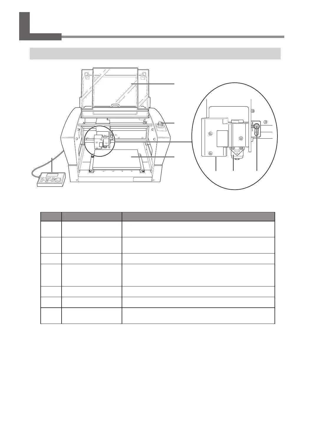
Front and Interior
Spindle head*
3
5
4
6 7
2
1
* In this document, the mechanisms around the spindle unit, including the spindle motor, are called the
"spindle head." Also, the rotary-axis area inside the spindle unit is called the "spindle."
No. Part Overview
1
Front cover
To ensure safety, opening this during engraving or spindle rotation
causes an emergency stop to occur.
2
Emergency stop button
Press this in an emergency to interrupt this machine's power supply.
" P. 13 “Emergency Stop to Ensure Safety”
3
Workpiece table The workpiece to be engraved is mounted on this table.
4
Handy Panel
This is used to perform tool movement and other machine
operations, and to make various settings.
" P.8 “Handy Panel”
5
Laser pointer Laser irradiation is applied from here.
6
Spindle unit Install the tool here.
7
Lock lever
This locks or unlocks the spindle head.
" P. 62 “Setting the Lock Lever”
Part Names and Functions
6
Chapter 1 Getting Started