The Machine Does Not Move When Engraving Data Is Sent ...................................................................... 127
The Spindle rotates but Does Not Move From Its Position When Engraving Data Is Sent ..............127
The Spindle Does Not Rotate .................................................................................................................................127
Descent Does Not Stop ............................................................................................................................................ 128
Loud Noise or Unpleasant Noise during Engraving ......................................................................................129
Troubleshooting (Engraving Quality Problems) ..............................................................................................................130
Engraving Is Not Performed on the Expected Position ................................................................................ 130
Cutting-in Depth Is Not Uniform (When Nose Unit Is Used) ......................................................................130
Cutting-in Depth Is Not Uniform (When Nose Unit Is Not Used) ..............................................................130
The Tool Leaves Tracks at Places Where Cutting-in Starts or Where Lines Change Direction ........131
An Engraved Bottom Surface Is Rough or Burring Remains ......................................................................131
Engraved Lines Are Uneven or Wavy ..................................................................................................................132
Troubleshooting (Installation) ................................................................................................................................................ 133
Driver Installation Is Impossible ............................................................................................................................133
Uninstalling the Driver .............................................................................................................................................137
Installing the Driver Separately.............................................................................................................................140
Installing the Software and the Electronic-format Manual Separately ..................................................142
Responding to an Error Message ..........................................................................................................................................144
"1000-000*" The % limit switch was not found. ..............................................................................................145
"1017-0000" The cover was opened during the spindle rotating. ............................................................145
"1023-0000" (RML-1) The number of the parameters is incorrect. ...........................................................146
"1024-0000" (RML-1) The parameter is out of range. ....................................................................................146
"1025-0000" (RML-1) A wrong command is detected...................................................................................147
"1029-0000" The spindle experienced an overload. ......................................................................................147
"102A-000*" The spindle experienced overcurrent. ......................................................................................148
"102B-0000" The spindle motor temperature is too high. ..........................................................................149
"102D-0000" The spindle cannot be turned. .................................................................................................... 150
"1044-0000" The automatic Z0 setting failed...................................................................................................150
Locations of the Power Rating and Serial Number Labels ...........................................................................................151
Connector Specications .........................................................................................................................................................152
Expansion Port ............................................................................................................................................................152
Machine Specications .............................................................................................................................................................153
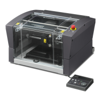
External View ...............................................................................................................................................................153
Work Area......................................................................................................................................................................154
Workpiece Table Installation Area Dimensional Drawing ...........................................................................155
Laser Pointer Irradiation Area ................................................................................................................................155
Main Specications ...................................................................................................................................................156
http://www.dgshape.com/
Copyright © 2018 DGSHAPE Corporation
Company names and product names are trademarks or registered trademarks of their respective holders.
Contents
3