2-7
CH 2/ Voltage Measurement Cables and Current Probe Connections
Connection
guidelines
Follow these guidelines when making voltage connections.
• Refer to the measurement cable set figure for probes that connect to input channel
connectors A, B, C, and D.
• Each channel input has plus (+) and minus (-) differential inputs of 1 to 1000 Vrms
max.
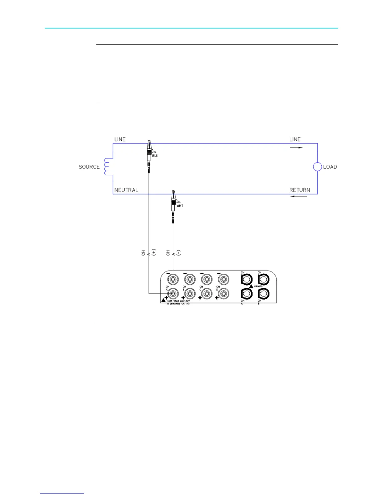
Example: Single
phase
connection
The following figure shows a voltage connection to a single phase circuit for channel
A.
HDPQ-901a
Shop for Power Metering products online at:
1.877.766.5412
www.PowerMeterStore.com
 Loading...