Electrical connection Proline Promass E 500 PROFIBUS PA
42 Endress+Hauser
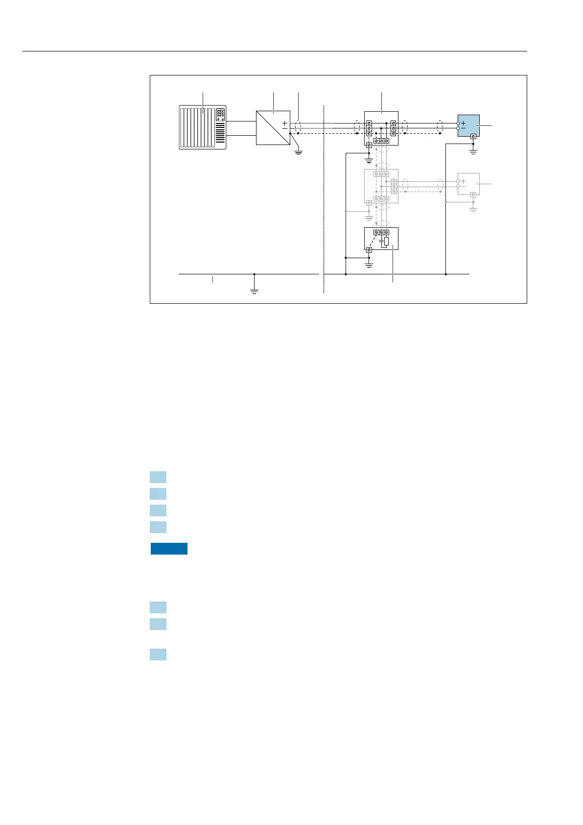
A0028768
17 Connection example for PROFIBUS PA
1 Control system (e.g. PLC)
2 PROFIBUS PA segment coupler
3 Cable shield: the cable shield must be grounded at both ends to comply with EMC requirements; observe cable
specifications
4 T-box
5 Measuring device
6 Local grounding
7 Bus terminator
8 Potential equalization conductor
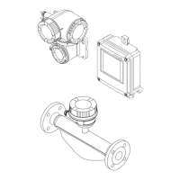
7.2.7 Preparing the measuring device
Carry out the steps in the following order:
1. Mount the sensor and transmitter.
2. Sensor connection housing: Connect connecting cable.
3. Transmitter: Connect connecting cable.
4. Transmitter: Connect signal cable and cable for supply voltage.
NOTICE
Insufficient sealing of the housing!
Operational reliability of the measuring device could be compromised.
‣
Use suitable cable glands corresponding to the degree of protection.
1. Remove dummy plug if present.
2. If the measuring device is supplied without cable glands:
Provide suitable cable gland for corresponding connecting cable.
3. If the measuring device is supplied with cable glands:
Observe requirements for connecting cables → 35.