Epson Artisan 810/835/837/710/725/730/Epson Stylus Photo PX810FW/TX810FW/PX820FWD/TX820FWD/PX830FWD/PX710W/TX710W/PX720WD/TX720WD/PX730WD/TX730WD
Revision G
DISASSEMBLY/ASSEMBLY Disassembly Procedures 149
Confidential
4.2.5.8 Lower ASF Paper Guide Assy
Parts/Components need to be removed in advance:
ADF Unit (Artisan 810/835/837/PX810FW/TX810FW/PX820FWD/TX820FWD/
PX830FWD only)/Scanner Unit/Upper Left Housing/Paper Guide Top Assy/
Upper Housing/Rear Left Housing/Left Housing/Decoration Belt/Power Supply
Unit/Rear ASF Paper Guide Cover
Removal procedure
1. Release the hooks (x2) and remove the Spur Gear A.
Figure 4-91. Removing the Lower ASF Paper Guide Assy (1)
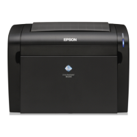
5. Insert the point A of the CR Porous Pad Assy to the point B of
the Ink System. After making sure that the porous pad of the
CR Porous Pad Assy touches the porous pad of the Ink System
shown in
Fig. 4-87, secure the CR Porous Pad Assy and the Ink
System together to the frame with the screw.
Figure 4-90. Installing the Ink System (4)
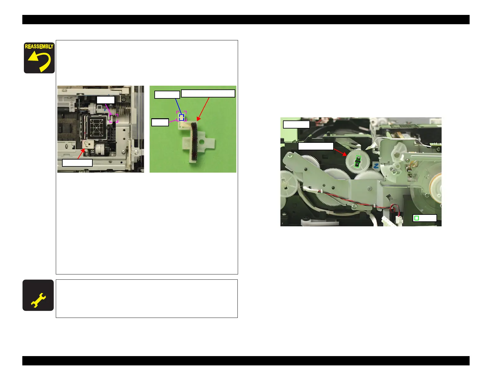
6. Push the switch lever in the direction of the arrow and turn the
spur gear (see
Fig. 4-88), then align the Transmission Arm to
the position A (Ink System operation point) shown in Fig. 4-89.
7. Connect the AID cable to the connector on the SUB Board, and
route the cable through the groove on the Base Frame. (See
Fig.
4-86.)
8. Visually check the cap section to make sure that the Ink System
is installed horizontally. If the cap surface is not horizontal, a
fatal error may occur due to interfering with the carriages or
print defect may occur because cleaning can not be performed
due to capping defect.
A D J U S T M E N T
R E Q U I R E D
After removing/replacing the Ink System, make the specified
adjustments. (See
Chapter 5 "ADJUSTMENT".)
Point A
CR Porous Pad Assy
Porous Pad

 Loading...