Epson Artisan 810/835/837/710/725/730/Epson Stylus Photo PX810FW/TX810FW/PX820FWD/TX820FWD/PX830FWD/PX710W/TX710W/PX720WD/TX720WD/PX730WD/TX730WD
Revision G
DISASSEMBLY/ASSEMBLY Disassembly/reassembly procedures specific to Artisan 710/PX710W/TX710W 193
Confidential
4.3.2.3 Card Slot Assy
Parts/Components need to be removed in advance:
Scanner Unit/Upper Left Housing/Paper Guide Top Assy/
Upper Housing/Hinge/Rear Right Housing/Right Housing/Main Board Unit/
CSIC Assy/Cartridge Box Unit/Ink Supply Tube Assy
Removal procedure
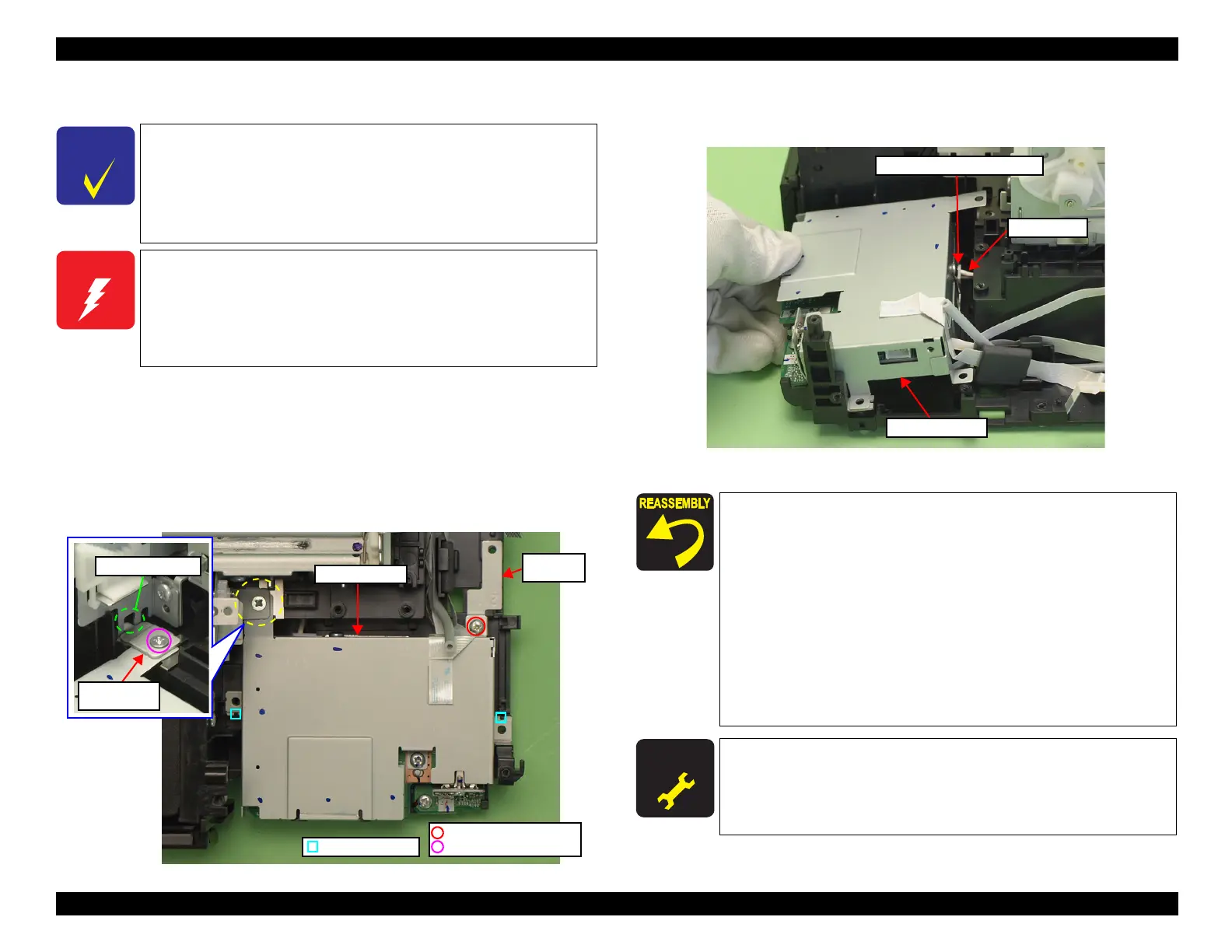
1. Remove the screws (x2) that secure the Card Slot Assy, and remove the
grounding plate and the EJ Release Frame Support.
Figure 4-189. Removing the Card Slot Assy (1)
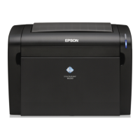
2. Disconnect the AID cable from the connector on the SUB Board, and remove
the Card Slot Assy.
Figure 4-190. Removing the Card Slot Assy (2)
The disassembly/reassembly procedures for Artisan 810/835/
837/PX810FW/TX810FW/PX820FWD/TX820FWD/
PX830FWD differ from those
for
Artisan 710/725/730/PX710W/
TX710W/PX720WD/TX720WD/PX730WD/TX730WD, see
"4.2.4.5 Card Slot Assy" (p.132) for the procedures.
The Card Slot Assy includes the SUB Board and the STG Board.
When powering this product, high-voltage current may be applied
on the SUB Board. To prevent ELECTRIC SHOCK, do not touch
the SUB Board section when the power is ON.
If the shock should happen, the flowing current is very tiny, about a
few hundreds
μA, therefore it will not do any harm on the human
body.
Dowel & Groove
Grounding
plate
Card Slot Assy
Protrusion and hole
EJ Release
Frame Support
C.F.B. 3x10 (6±1Kgfcm)
C.B.P. 3x8 (6±1Kgfcm)
Connect the AID cable properly to the connector on the SUB
Board. (See
Fig. 4-190.)
Align the grooves (x2) of the Card Slot Assy with the dowels (x2)
of the Base Frame. (See
Fig. 4-189.)
When attaching the grounding plate, install it over the Card
Slot Assy, and tighten them together with the screw. (See
Fig.
4-189.)
When attaching the EJ Release Frame Support, insert the
protrusion of the EJ Release Frame Support to the hole of the
Main Frame, and then secure them with the screw. (See
Fig.
4-189.)
For routing the FFCs, see "4.4 Routing FFC/cables" (p.196).
A D J U S T M E N T
R E Q U I R E D
After removing/replacing the Card Slot Assy, make the specified
adjustments. (See
Chapter 5 "ADJUSTMENT".)
AID cable
Card Slot Assy
Connector on the SUB Board

 Loading...