45
MB1 User Manual
© 2016 Expert Electronics
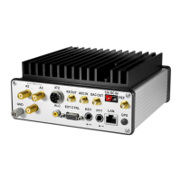
REAR PANEL DESCRIPTION
1) HF1-HF4 - HF antenna connectors.
Connect receiving and transmitting HF antennas to the HF1-HF4 connectors. The antennas'
impedance should be 50 Ohm.
You can select each of the antenna connectors using the ANT button on the front panel of
the transceiver when in HF mode (more details in Antenna switching ).
Note:
(
Using an Antenna impedance different from 50 Ohm may lead to deterioration of the
receiving capabilities of the transceiver and degradation of the quality of the transmitted
signal.
2) VHF1-VHF2 - VHF antenna connectors.
Connect receiving and transmitting VHF antennas to the VHF1-VHF connectors. The antennas'
impedance should be 50 Ohm.
You can select each of the antenna connectors using the ANT button on the front panel of the
transceiver when in VHF mode (more details in Antenna switching ).
Note:
(
Using an Antenna impedance different from 50 Ohm may lead to deterioration of the
receiving capabilities of the transceiver and degradation of the quality of the transmitted
signal.
3) GND - Grounding/Earth terminal.
Use the GND terminal for grounding the transceiver.
Attention!
i
To eliminate the risk of electric shock, reliable grounding of transceiver is
required!
4) PA PTT 1-4 - PTT keys for external Power Amplifiers switching in TX mode.
Connect an external Power Amplifier to one of the PA PTT keys to allow the transceiver to
switch the PA to transmitting mode (more details in Linear Amplifier ).
5) ALC - Automatic Level Control.
Connect to the ALC output of the Power Amplifier for automatic control of the transceiver
output power.
Input voltage range 0...-4 V.
167
167
21