46
MB1 User Manual
© 2016 Expert Electronics
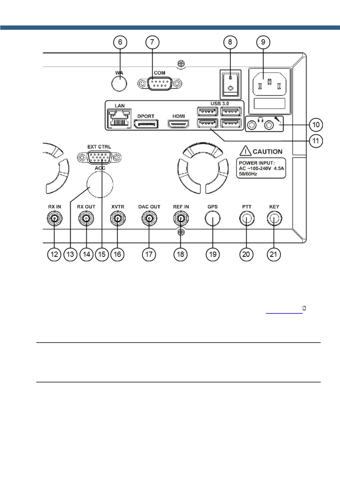
REAR PANEL DESCRIPTION
6) WA - Connector for embedded WLAN module.
Not available in this revision of the MB1.
7) COM - COM-port connector.
The COM-port connects to external devices to control them (more details Rear-Panel) .
8) I/O - Power switch
Select the I position to apply power to the transceiver.
Note:
(
Make sure that the rear power switch is in I position before pressing the power button on the
front panel of the transceiver.
9) Transceiver's power connector.
Connect the transceiver to the AC mains using the cable from the kit.
The supply voltage range is 100-240 V. Frequency 50/60 Hz. Current up to 4.5 A.
There is a 5A fuse installed in the power connector.
19