(1) Reconnect the host after loading this command.
Programming steps of frequent used commands:
Reading a weight value:
1. Read 40009 and 40010.
2. Check error status,
3. error, read the weight value (gross, net or tare),
4. If there is an error, check the error code.
Zero Calibration procedure:
1. Check the bit B0 of 40195 which should be '1' to start adjustment.
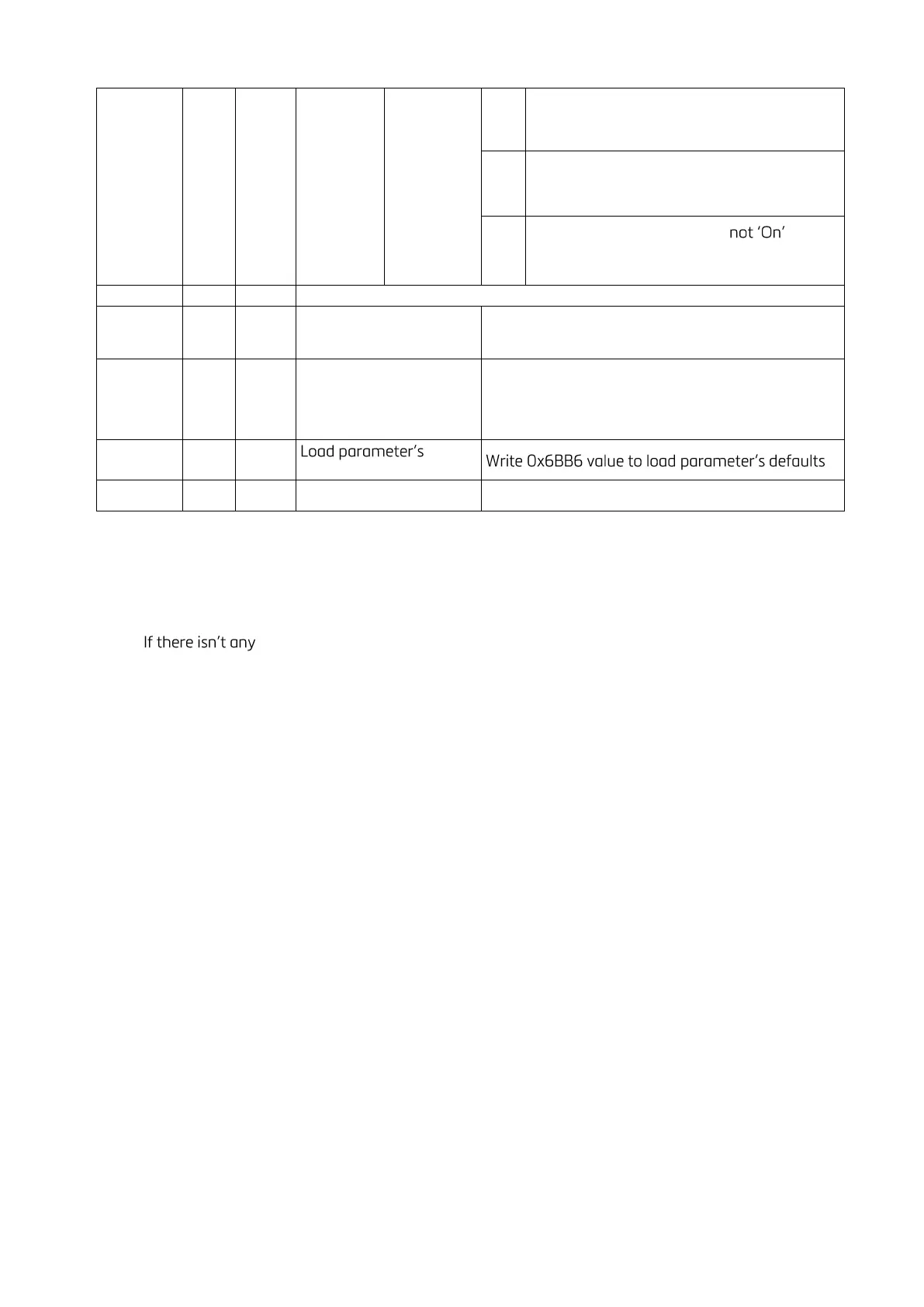
2. Load the decimal '188' to 40185 to start Zero calibration.
3. Check the bit B1 of 40195 which is '1' during zero calibration process.
4. The bit B0 of 40195 changes to '1' at the end of the Zero calibration.
5. If one of error bits (B3 ~ B10) of 40195 is '1', check error code to understand the calibration error.
Span Calibration procedure:
1. Check the bit B0 of 40195. it should be '1' to start adjustment.
2. First load the span value to 40187-188 and then load the decimal '220' to 40185 to start Span
calibration.
3. Check the bit B2 of 40195 which is '1' during span calibration process.
4. The bit B0 of 40195 changes to '1' at the end of the Span calibration.
5. If one of error bits (B3 ~ B10) of 40195 is '1', check error code to understand the calibration error.
EXPLANATION:
Attention: For hardware connection details, please refer to the related hardware descriptions in this manual.
Exception codes:
1: Function code is not supported.
2: Out of beginning and ending address range.
3: Invalid value entrance or wrong byte number.
4: Operation error.