181
16-3. VDCP Control
Installing VDCP Control Function to the HVS-3800HS/S enables VDCP control based on the
Video Disk Control Protocol (Harris/Louth).
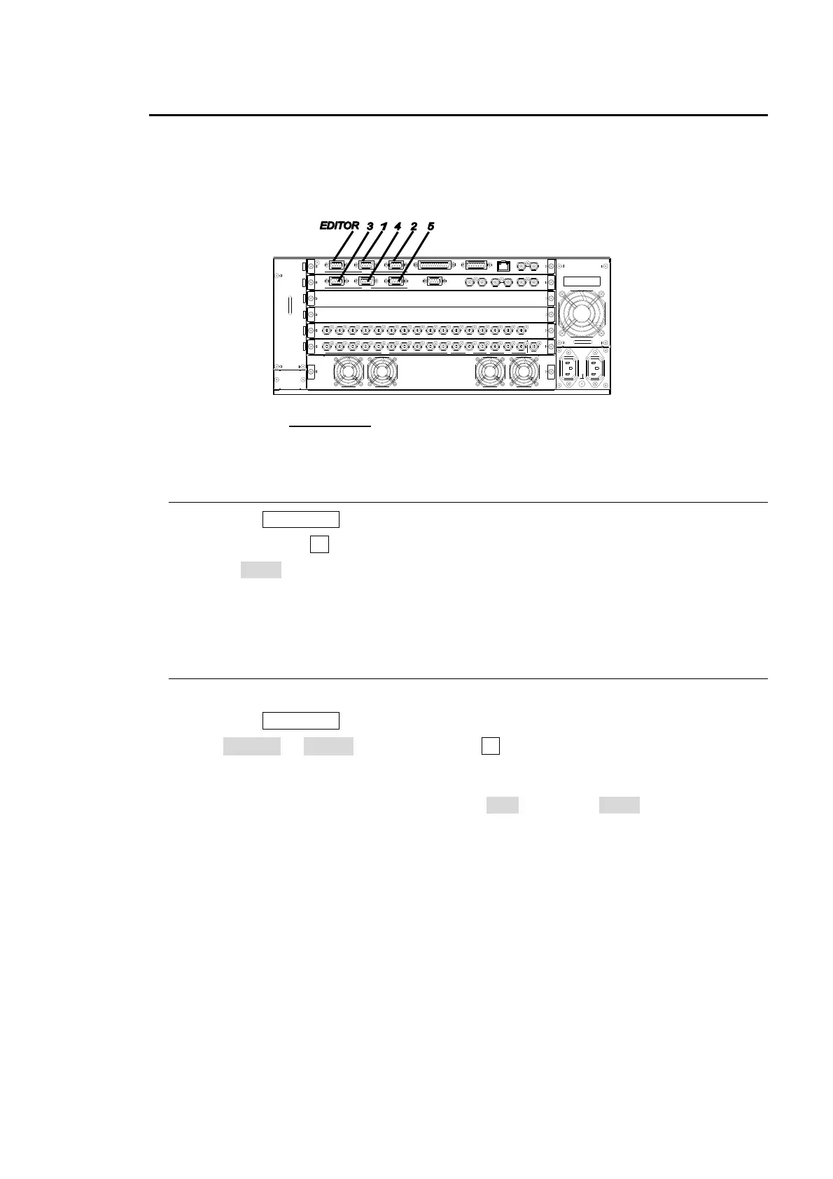
To use VDCP control, the HVS-3800HS/S rear outputs need to be connected to the VDCP
devices. Up to 5 VDCP devices can be configured.
Connect the RS-422
ports 1 to 5 on the HVS-3800HS/S rear panel and VDCP device with an
RS-422 straight cable. Refer to the manual supplied for connection on the VDCP side.
16-3-1. Assigning VDCP Control Function to Serial Port
Press the MU SETUP button in the menu section to display the MU SETUP top page.
Press the control F1 or the DOWN button to display the MU SETUP-RS-422 menu.
Select VDCP under the RS-422 serial port where the VDCP device is connected.
Reboot the MU after making the settings. (Note that the settings do not take effect until
the unit is rebooted.)
16-3-2. RS-422 Port Setting
Follow the procedure below to make RS-422 port settings.
Press the MU SETUP button in the menu section to display the MU SETUP top page.
Set SELECT to RS-422. Press the control F1 or the DOWN button to display the MU
SETUP-RS-422 menu.
Make the settings for the port that was assigned the VDCP control function in the
previous section. Normally the settings are ODD parity and 38400 for the baud rate.
Settings may differ for some VDCP devices.
Reboot the MU after making the settings. (Note that the settings do not take effect until
the unit is rebooted.)
OUTP UT
OUT PUT
1
INP UT 1
INP UT
2345
1
GENLOCK
GL
2345
RS-422
CPU
CPU
3
EDITOR
4
RS-422
1
AUX
67 89
M/E1
10 PGM PREV CLEAN
6 7 8 9 10 11 12 13
M/E2
CLE AN
PGM
PREV SD SDI OUT
2
1
14 15 16
RATING LABEL
GPI/TALLY OUT
ALARM5
2
TR I SYNC IN
GP I IN
(10/100BASE-T)
BB IN
LAN 1
1
REF OUT
2
ARCNET
AC100-240V 50/60Hz IN

 Loading...


