184
16-4. Router Control
Router Control feature allows the user to control a routing switcher remotely via the RS-422
serial connection. A Free Assign function is also provided to enable its operation from the control
panel. This allows the switcher operator to easily control the signal routing from the panel.
IMPORTANT
Note that this router control feature supports the HARRIS Integrator Series of
Routing Switchers only.
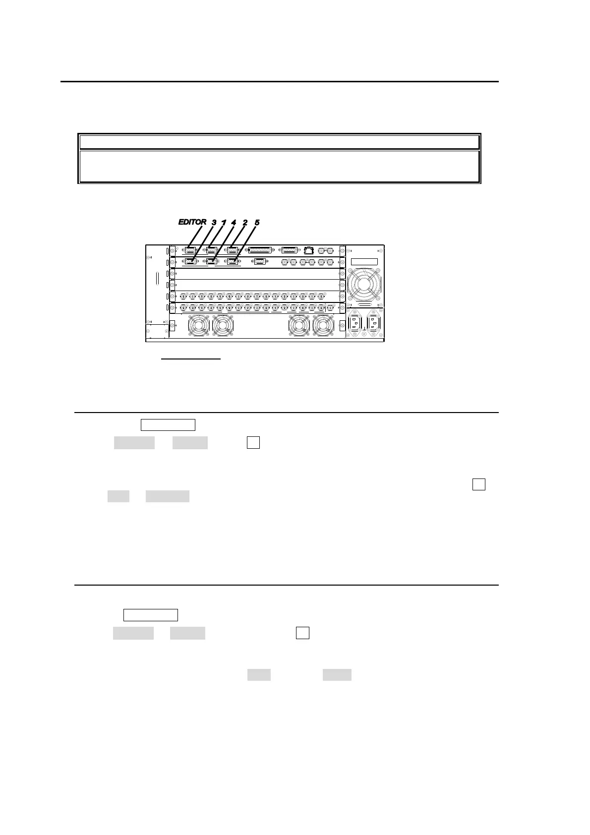
To use signal routing control, the HVS-3800HS/S needs to be connected to an RS-422 serially
controlled routing switcher using an RS-422 port on the rear panel.
Connect the RS-422
ports 1 to 5 on the HVS-3800HS/S rear panel and the routing switcher
with an RS-422 crossover cable. Refer to the manual supplied for connection on the router side.
16-4-1. Assigning Routing Control to Serial Port
Press the MU SETUP button in the menu section to display the MU SETUP top page.
Set SELECT to RS-422. Press F1 or the DOWN button to display the MU SETUP-
RS-422 menu.
Assign the ROUTING function to the RS-422 serial port where the routing switcher is
connected by selecting the router under the target RS-422. For example, turn the F2 to
set No.2 to ROUTER (if the router is connected to the RS-422 (2) port on the MU rear
panel.)
Reboot the MU after making the settings. (Note that the settings do not take effect until
the unit is rebooted.)
16-4-2. RS-422 Port Setting
Follow the procedure below to make RS-422 port settings.
Press MU SETUP to display the MU SETUP top page.
Set SELECT to RS-422. Press the control F1 or the DOWN button to display the MU
SETUP-RS-422 menu.
Make the settings for the port that was assigned the VTR control function in the previous
section. Normally the settings are ODD parity and 38400 for the baud rate. Settings may
differ for some VTRs.
Reboot the MU after making the settings. (Note that the settings do not take effect until
the unit is rebooted.)
OUTP UT
OUT PUT
1
INP UT 1
INP UT
2345
1
GENLOCK
GL
2345
RS-422
CPU
CPU
3
EDITOR
4
RS-422
1
AUX
67 89
M/E1
10 PGM PREV CLEAN
6 7 8 9 10 11 12 13
M/E2
CLE AN
PGM
PREV SD SDI OUT
2
1
14 15 16
RATING LABEL
GPI/TALLY OUT
ALARM5
2
TR I SYNC IN
GP I IN
(10/100BASE-T)
BB IN
LAN 1
1
REF OUT
2
ARCNET
AC100-24 0V 50/60Hz IN

 Loading...


