7
2-2-3. Interfaces
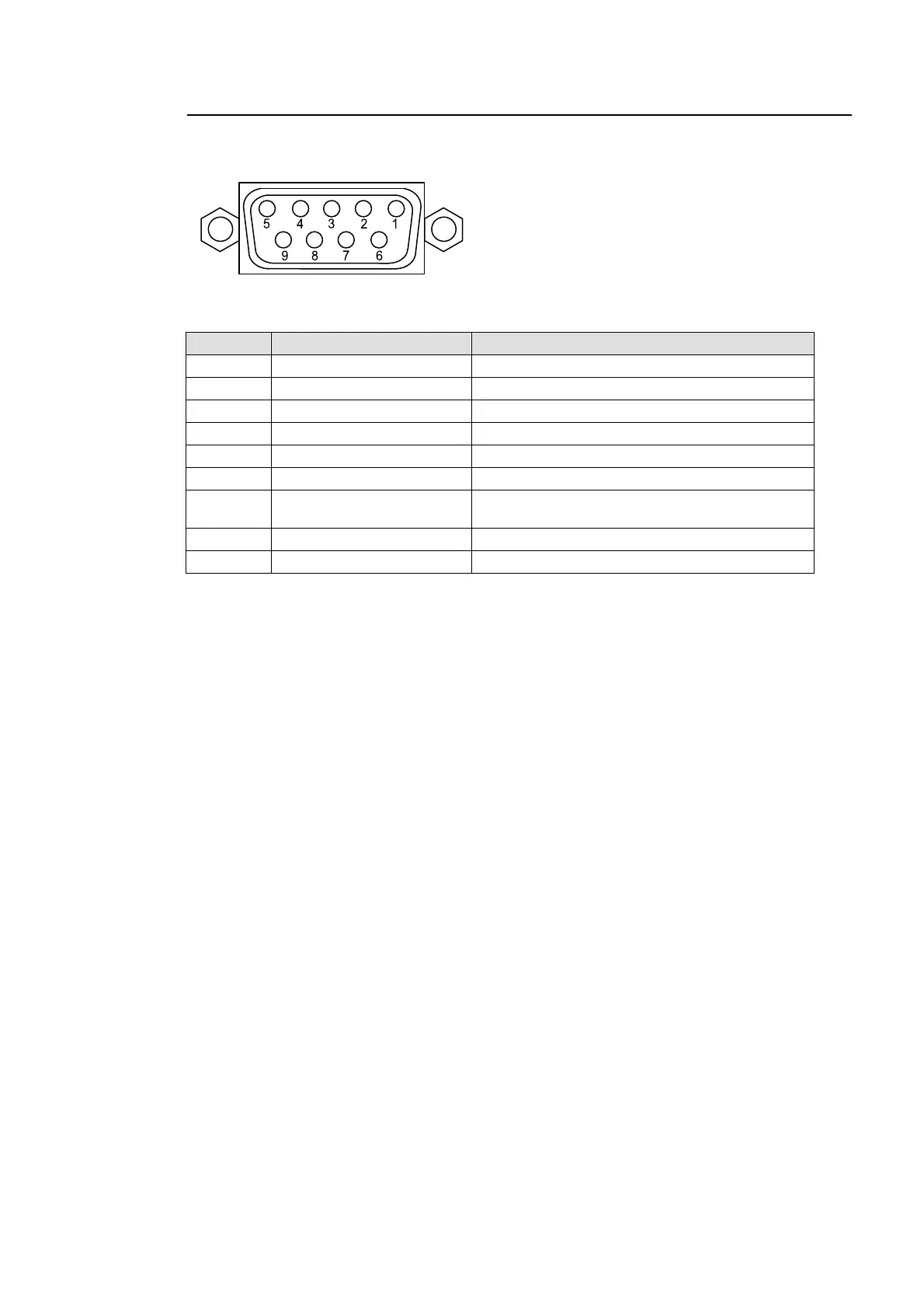
ALARM Connector
Pin Assignment Table (9-pin D-sub female)
Pin No. Signal Name Description
1 FAN ALARM OUT Fan failure alarm. Normally open.
2 POWER ALARM OUT Power supply failure alarm. Normally open.
3 EXT ALARM COMMON Not used
4 EXT ALARM OUT Not used
5 RESET IN External reset input. Active low initiate.
6 FAN ALARM COMMON Fan alarm common.
7
POWER ALARM
COMMON
Power supply alarm common.
8 GND Common ground
9 GND Common ground
* Load current rating (per pin): 0.5A.
Cable Connectors
9-pin D-sub connector (male) with inch security lock screws needed for user cable
fabrication.
Fan alarm
Pins 1, 6 remain OPEN during normal operation. If fan failure occurs at HVS-3800HS/S side,
pins 1, 6 will short and fan alarm signal output occurs.
Power supply alarm
Pins 2, 7 remain OPEN during normal operation. If a power supply failure occurs, pins 2, 7
will short and power supply alarm signal output occurs.
External reset
External reset signal input to pin 5, shorts pin 8 to pin 9. MU reset occurs when short initiated.

 Loading...


