En-12
Custom code setting for indoor unit
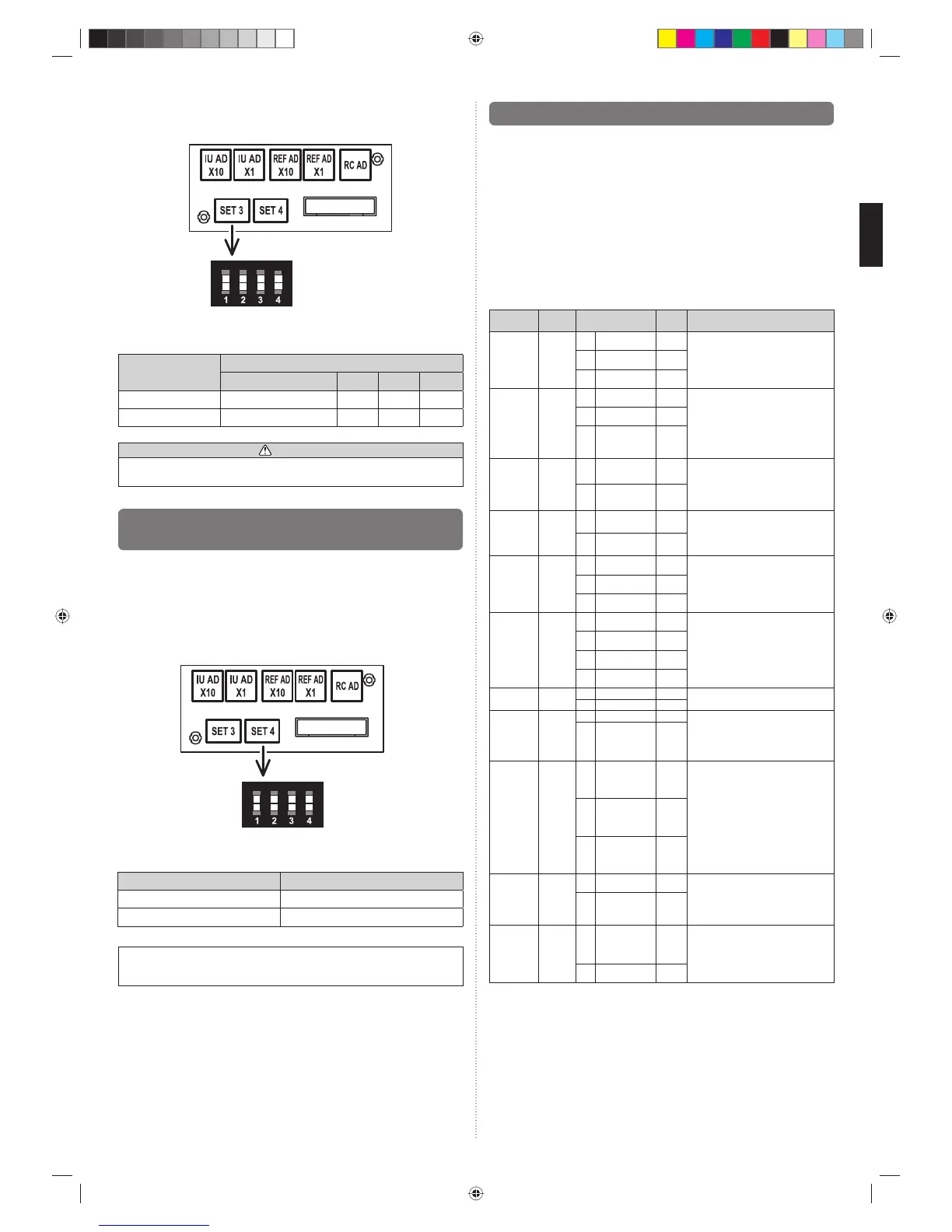
Set the DIP switch SET 3 SW1 , SW2, referring to the Table B.
ON
OFF
SW
1
SW
2
SW
3
SW
4
DIP switch “SET3”
Table B
Custom code
A (Factory setting) B C D
DIP switch SET 3 SW1 OFF ON OFF ON
DIP switch SET 3 SW2 OFF OFF ON ON
CAUTION
• Do not operate any switches other than prescribed, as it can cause the unit to
operate improperly or malfunction.
7.3. Switching the upper limit of cooling
temperature
This setting can be raised the upper limit of the cooling temperature setting range.
This setting can be used when connecting to the following controllers.
• Wired remote controller (2-wire type)
• Central remote controller
• Touch panel controller
• System controller
• Service tool
• Web monitoring tool
DIP switch setting
Set the DIP switch SET 4 SW3 referring to the Table C.
DIP switch “SET4”
SW
1
SW
2
SW
3
SW
4
ON
OFF
Table C
DIP switch SET 4 SW3 Cooling temperature setting range
OFF (Factory setting) Standard (18 to 30 °C)
ON Extension (18 to 32 °C)
NOTE :
Please do not make a standard setup and an extension setup intermingled in remote
controller group.
7.4. Function setting
• FUNCTION SETTING can be performed with the wired or wireless remote controller.
(The remote controller is optional equipment)
• Refer to the wired or wireless remote controller manual for detailed setting information.
(Set IU AD ,REF AD SW to 0)
• Refer to “7.1. Setting the address.” for indoor unit address and refrigerant circuit
address settings.
• Turn the power of the indoor unit ON before starting the setting.
* Turning on the power to the indoor units initializes EEV, so make sure the piping air
tight test and vacuuming have been conducted before turning on the power.
* Also check again to make sure no wiring mistakes were made before turning on the
power.
Function details
Function
Function
number
Setting number Default Details
Filter indica-
tor interval
11
00 Default ○
Adjust the fi lter cleaning interval
notifi cation. If the notifi cation is too early,
change to setting 01. If the notifi cation is
too late, change to setting 02.
01 Longer
02 Shorter
Filter indica-
tor action
13
00 Enable ○
Enable or disable the fi lter indicator. Set-
ting 02 is for use with a central remote
controller.
01 Disable
02
Display only on
central remote
controller
Ceiling
airfl ow
20
00 Default ○
Regulate the airfl ow according to the
needs of the installation location. When
set to 01, the air fl ow will be stronger.
(Cassette type only)
01 High Ceiling
Vertical
airfl ow direc-
tion
23
00 Default ○
Adjust the vertical airfl ow direction. All
airfl ow direction louvers are adjusted
together.
(Cassette type only)
01 Raise
Cool air
temperature
trigger
30
00 Default ○
Adjust the cool air trigger temperature.
To lower the trigger temperature, use
setting 01. To raise the trigger tempera-
ture, use setting 02.
01 Adjust (1)
02 Adjust (2)
Heat air
temperature
trigger
31
00 Default ○
Adjust the heat air trigger temperature.
To lower the trigger temperature by 6
degrees C, use setting 01. To lower the
trigger temperature by 4 degrees C, use
setting 02. To raise the trigger tempera-
ture, use setting 03.
01 Adjust (1)
02 Adjust (2)
03 Adjust (3)
Auto restart 40
00 Enable
Enable or disable automatic system
restart after a power outage.
01 Disable ○
Cool Air
Prevention
43
00 Super low ○
Restrain the cold airfl ow with making
the airfl ow lower when starting
heating operation. To correspond to
the ventilation, set to 01.
01
Follow the
setting on
the remote
controller
External
control
46
00 Start/Stop ○
Allow an external controller to start
or stop the system, or to perform an
emergency stop.
* If an emergency stop is performed
from an external controller, all refrig-
erant systems will be disabled.
* If forced stop is set, indoor unit
stops by the input to the external
input terminals, and Start/Stop by a
remote controller is restricted.
01
Emergency
stop
02 Forced stop
Error report
target
47
00 All ○
Change the target for reporting errors.
Errors can either be reported in all loca-
tions, or only on the wired remote.
01
Display only on
central remote
controller
Fan set-
ting when
cooling
thermostat
OFF
49
00
Follow the
setting on
the remote
controller
○
When set to 01, the fan stops when
the thermostat is OFF in cooling op-
eration. Connection of the wired re-
mote controller (2-wire type or 3-wire
type) and switching its thermistor are
necessary.
01 Stop
9371022253-01_IM.indb Sec1:129371022253-01_IM.indb Sec1:12 2012-7-12 14:34:452012-7-12 14:34:45
 Loading...