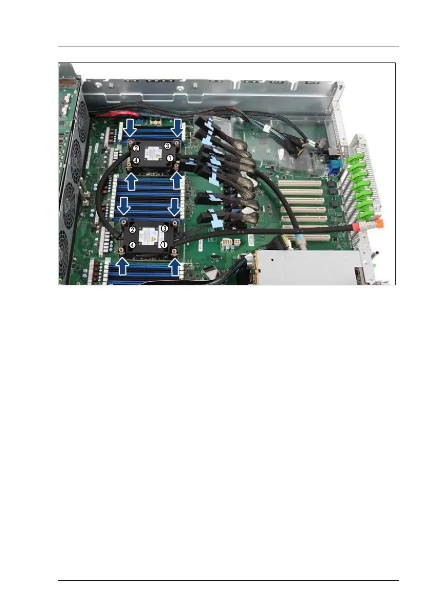
Figure 178: Installing the LC kit - example: bottom system board
▶
Push the four latches inward.
▶
Carefully place the LC heat sink onto the CPU socket.
▶
Push the four latches outward.
▶
Fasten the four captive screws in the sequence printed on the heat sink (1 to
4).
T
ool: T
orx 30 screw driver
Torque: 0.9 - 1.0 Nm
▶
Proceed for the second LC heat sink in the same way.
▶
Remove the orange protective caps from the tube connectors.
Liquid cooling (LC)
RX4770 M6 Upgrade and Maintenance Manual 291

 Loading...