SECTION 8: Specifications and Safety
2025653-048 Revision B Responder
™
2000 Page 114
Connectors
The following sections describe connectors in the subassemblies within Responder 2000 Defibrillator.
Case
The case serves both as a housing and mechanical structure for the Responder 2000.
Power Connector – IEC 320 type – AC Power
Connector: Heyco 0916
Pin Number Name Description
1 AC1
2 AC2
AC1 – AC2: 90-264VAC, 47-63Hz, <10A.
AC1 or AC2 to GND: <264VAC.
3 GND Earth ground connection
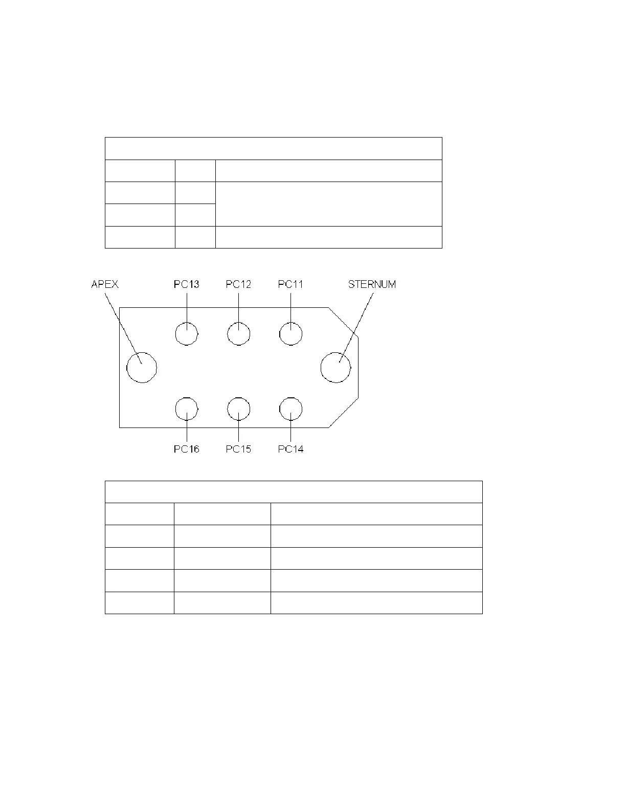
Paddles/Pads Connector – GE Defibrillator Paddles
View looking at socket on the back of the Responder 2000
Connector: GE 43252483
Pin Number Name Description
PC11 SW_CHG/SHCK Pull Down Input – Charge/Shock Button
PC12 SW_SHCK Pull Down Input – Shock Button
PC13 N/A Not Used
PC14 ID_PADS/SPNS Pull Down Input – ID Bit – Pads