SECTION 8: Specifications and Safety
2025653-048 Revision B Responder
™
2000 Page 130
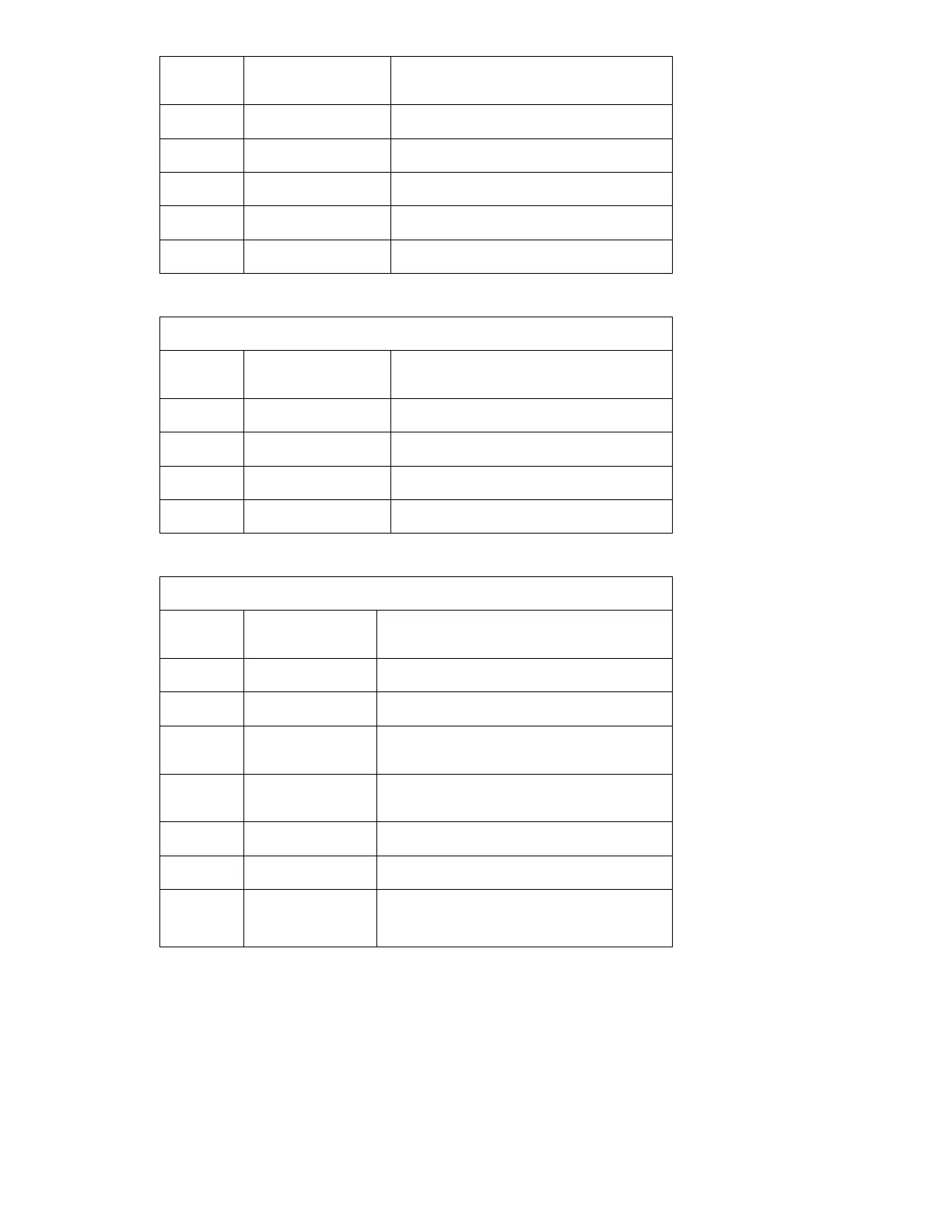
Pin
Number
Name Description
1, 2, 3, 4 GND System Ground
5 BAT_TEMP Input – 10K to Ground
6 SMBUS_DATA Bi-directional – SMBus Data
7 SMBUS_CLK Bi-directional – SMBus Serial Clock
8, 9, 10 +12V_BAT Battery Positive
J303 – Therapy power
Molex 39-30-3047
Pin
Number
Name Description
1 GND System Ground
2 +12V_SW Power Output
3 +12V_SW Power Output
4 GND System Ground
J311 – Power Control interface from main CPU PCBA
AMP 1-103673-3
Pin
Number
Name Description
1 +12V_UNSW Power Output – Power always present.
2, 3, 4 GND System Ground
5, 6, 7 +12V_SW Power Output – Power switched on Power Control
PCBA
8 /PWR_ON Input – Active low control to power switch on the
Power Control PCBA.
9 SMB_DAT Bi-directional – SMBus Data
10 SMB_CLK Input – SMBus Serial Clock
11 SERV_TX Service Port Tx
RS232 Data From Main PCBA