SECTION 8: Specifications and Safety
2025653-048 Revision B Responder
™
2000 Page 127
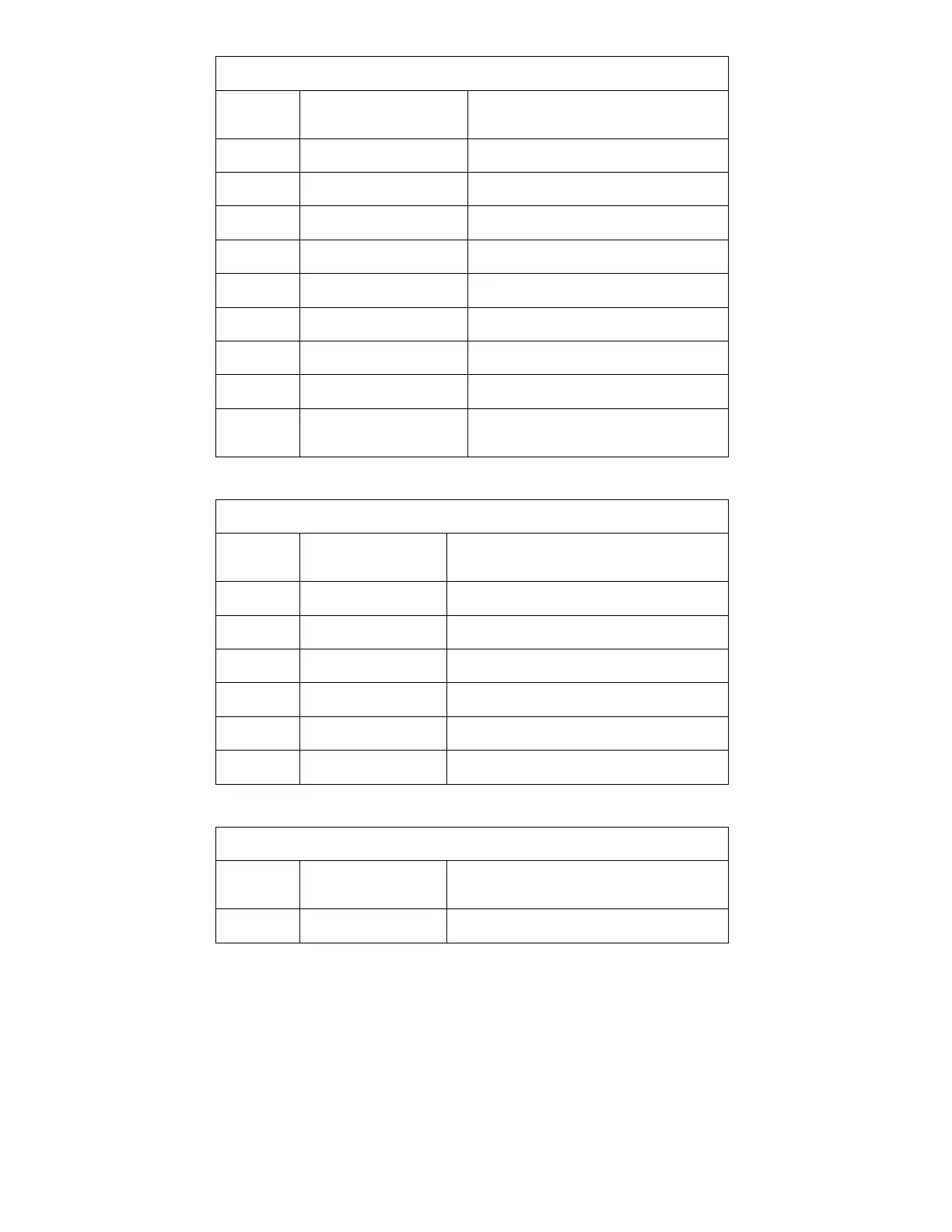
Molex 52610-2090
Pin
Number
Name Description
8 GND System Ground
9 PDL_ID_PC5 Pull Down Input – Paddle ID bit
10 PDL_ID_PC4 Pull Down Input – Paddle ID bit
11 PDL_CHGSHCK Pull Down Input – Button – Charge/Shock
12 PDL_SHCK Pull Down Input – Button – Shock
13 PDL_ID_PC6 Pull Down Input – Paddle ID bit
14, 15 PDL_GND System Ground
16-19 NC No Connection
20 THP_PRSNT_GND Grounded output to Therapy – Looped back
on THRP_/PRSNT
J109 – Paddles Control Connector
AMP 103670-7
Pin
Number
Name Description
8 PDL_CHGSHCK Pull Down Input – Button – Charge/Shock
7 PDL_SHCK Pull Down Input – Button – Shock
6 PDL_ID_PC6 Pull Down Input – Paddle ID bit
5 PDL_ID_PC4 Pull Down Input – Paddle ID bit
3 PDL_ID_PC5 Pull Down Input – Paddle ID bit
1, 2, 4 PDL_GND Paddle Control Ground – Isolated from Patient
J101, J102, J108 – Paddles HV Connectors
Keystone 1287-ST
Pin
Number
Name Description
J101 PDLHV_STERN Patient Connection – Sternum