SECTION 8: Specifications and Safety
2025653-048 Revision B Responder
™
2000 Page 124
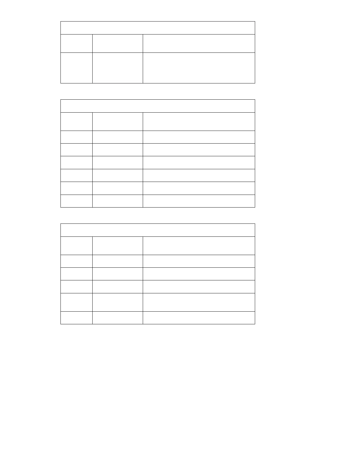
Molex 39-51-3263
Pin
Number
Name Description
6, 9, 10,
12, 14,
16, 19, 21
GND System Ground
J220 – PRINTER MOTOR
JST S6B-PH-K-S
Pin
Number
Name Description
1 COIL1A Output – Motor Coil 1 – Pos
2 COIL1B Output – Motor Coil 1 – Neg
3 COIL2A Output – Motor Coil 2 – Pos
4 COIL2B Output – Motor Coil 2 – Neg
5 DOORSW Pull Down Input – Door Switch
6 GND System Ground
J221 – SpO
2
INTERFACE
SAMTEC ESW-107-44-S-D
Pin
Number
Name Description
8 RxD Output - Isolated Logic Level Serial
9 TxD Input - Isolated Logic Level Serial
10, 13 +5V Isolated Power Output
2, 3, 5, 11,
12, 14
GND Isolated Ground
1, 4, 6, 7 NC No Connection