SECTION 4: Repair
2025653-048 Revision B Responder
™
2000 Page 31
Assembly
Overview
The following section details the assembly steps starting from a fully disassembled Responder 2000. When replacing a
single board or other component, not all reassembly steps may be applicable.
WARNING: Lethal Shock Hazard.
In the event of equipment failure, the two main capacitors may retain dangerous voltages even if the Responder
2000 is disconnected from AC power and the battery is removed. Normally, the capacitors are discharged when
power is shut off; however, it is possible for equipment damage to prevent the capacitors from discharging
properly.
Always assume the capacitors are fully charged.
Caution: Shock Hazard or Equipment Damage.
Before opening the case, ensure the AC power cord is disconnected and the battery is removed.
Caution: Procedure Failure.
Even though some assembly steps may not be applicable to a specific replacement procedure, all other steps
must be performed in the order listed.
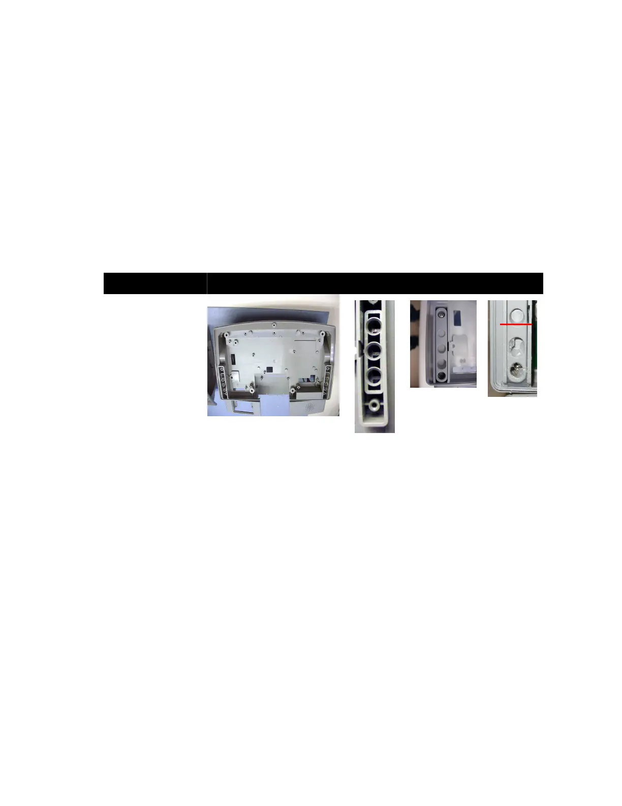
Paddle Latch Assembly
Assembly Step Details
Install Paddle Latch,
three springs, and
Paddle Latch Retainer
(using two Phillips
screws) on each side of
the Front Body.
Note: Ensure the
Paddle Latches are
oriented correctly and
the Paddle Latch notch
fits into the grove on
the Front Body.
Apply Silicone sealant
to the lower half of the
joint between the Front
Body and the Paddle
Latch Retainer.
Note: The seal must be
complete (no gaps).
Figure 1: Front Body Assembly
(Front View)
Figure 2:
Orientation
Detail
Figure 3:
Assembled
Latch
Figure 4:
Silicone
Application