SECTION 8: Specifications and Safety
2025653-048 Revision B Responder
™
2000 Page 123
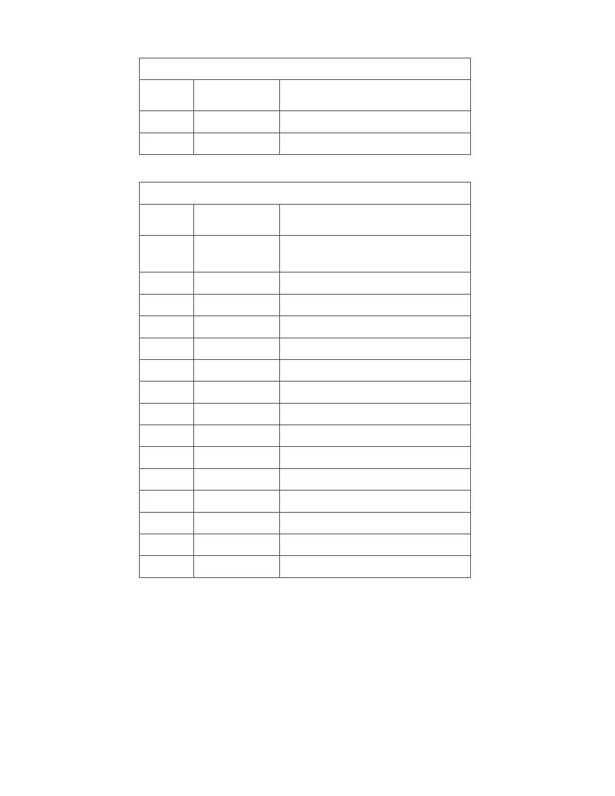
J216 – SPEAKER
AMP 103638-1
Pin
Number
Name Description
1 SPEAKER1 Output – Audio
2 SPEAKER2 Output – Audio
J219 – PRINTER HEAD
Molex 39-51-3263
Pin
Number
Name Description
1, 2,
25, 26
+5V_PWR Power Output – Print head high current supply.
24 +5V_DIG Power Output – Print head digital supply.
3 CLK Output – Pixel clock
4 STROBE Output – Shift Register Latch
5 DIN Output – Serial Pixel Data
7 OE_0-63 Output – Pixel Burn – Pixels 0-63
8 OE_64-127 Output – Pixel Burn – Pixel 64-127
11 OE_128-191 Output – Pixel Burn – Pixel 128-191
13 THRMSTR Input – Thermistor (to Ground)
15 OE_192-255 Output – Pixel Burn – Pixel 192-255
17 OE_256-319 Output – Pixel Burn – Pixel 256-319
18 OPTO_COL Input – Open Collector Active Low paper sense.
20 PAPER_LED Output – LED Drive – Paper sensor.
22 OE_320-383 Output – Pixel Burn – Pixel 320-383
23 DOUT Input – Return from end of shift register.