SECTION 8: Specifications and Safety
2025653-048 Revision B Responder
™
2000 Page 125
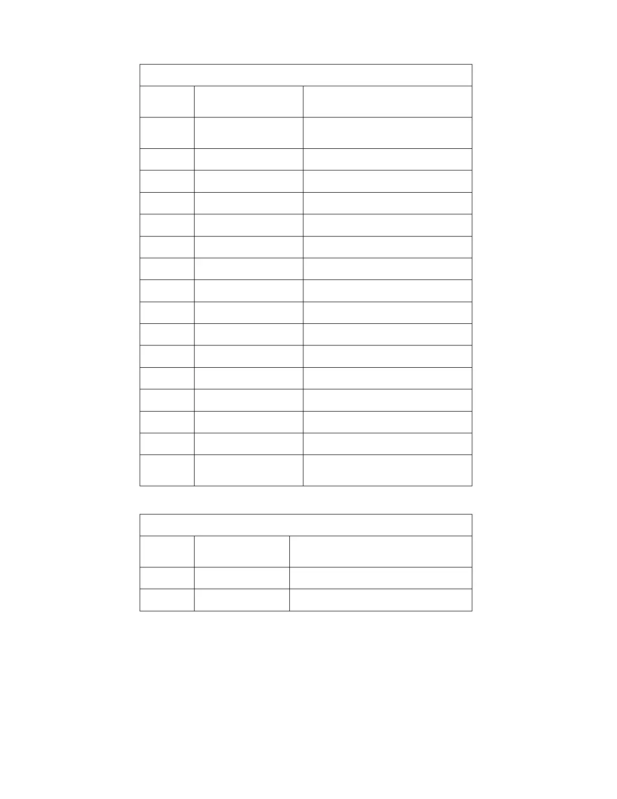
J210 – THERAPY PCBA
MOLEX 52610-2090
Pin
Number
Name Description
1 THRP_/PRSNT Pull Down Input – Therapy PCBA plugged
in
2 THRP_HVEN Output – HV enable
3 THRP_/SHOCK Output – Shock enable (active low)
4 THRP_ISOPWRON Output – Therapy isolated power enable
5 THRP_Rx Input – Logic Level Serial
6 THRP_Tx Output – Logic Level Serial
7 +3.3V Power Output
8 GND System Ground
9 PDL_ID_PC5 Pull Down Input – Paddle ID bit
10 PDL_ID_PC4 Pull Down Input – Paddle ID bit
11 PDL_CHGSHCK Pull Down Input – Button – Charge/Shock
12 PDL_SHCK Pull Down Input – Button – Shock
13 PDL_ID_PC6 Pull Down Input – Paddle ID bit
14, 15 PDL_GND System Ground
16-19 NC No Connection
20 THP_PRSNT_GND Grounded output to Therapy – Looped back
on THRP_/PRSNT
J212 – ECG PCBA
SAMTEC DW-04-11-F-D-500
Pin
Number
Name Description
2 TxD Output - Logic Level Serial
4 RxD Input - Logic Level Serial