SECTION 8: Specifications and Safety
2025653-048 Revision B Responder
™
2000 Page 118
MAIN CPU PCBA
The main CPU PCBA is the nucleus of the system, with all major subsystems connecting to this board.
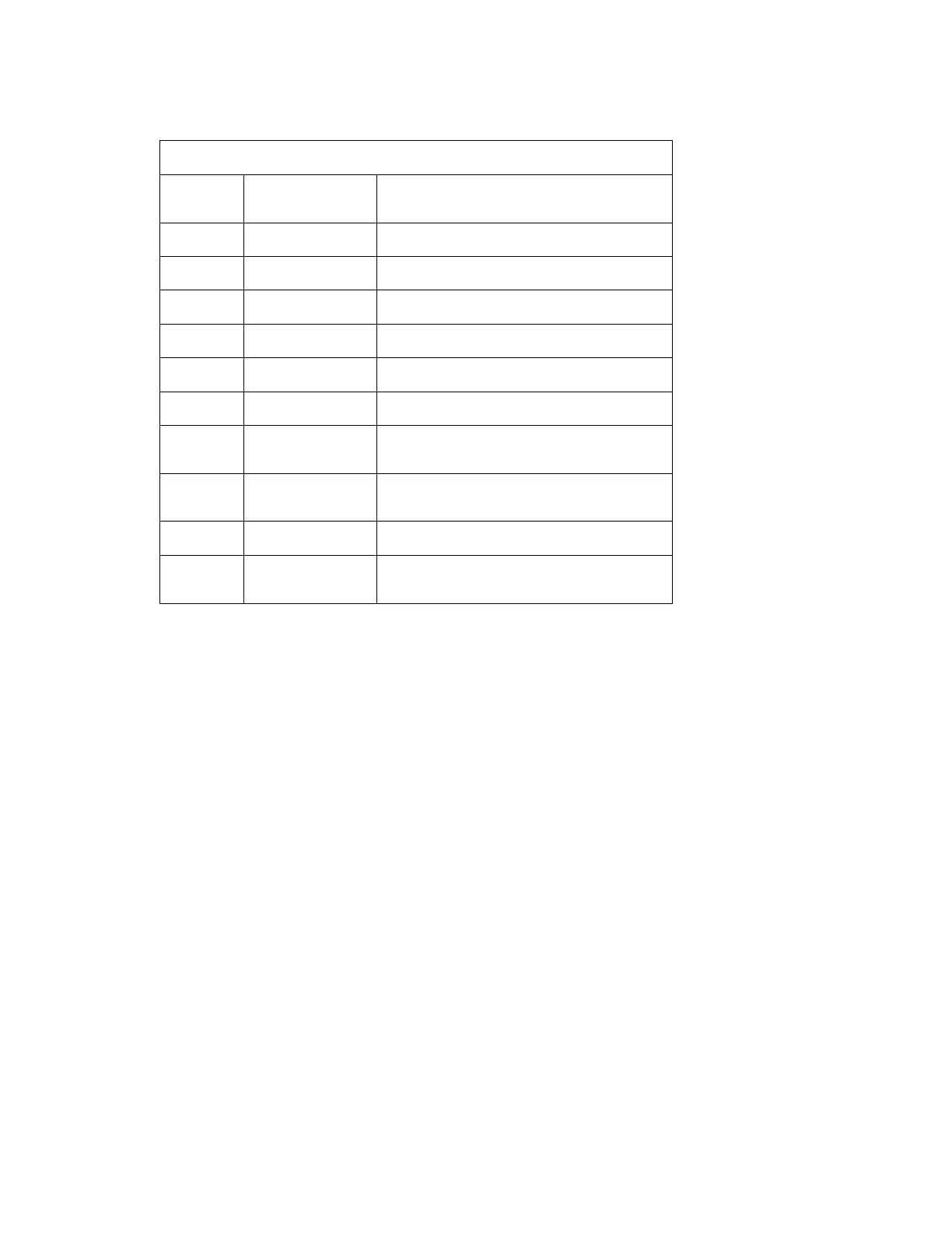
J211 - Power Control Interface to Power Control PCBA
AMP 1-103638-3
Pin
Number
Name Description
1 NC Not Used
2 Fan_/Drive Pull Down Active Fan Drive
3 Serv_DCE_Rx RS232 Serial input from Service Connector.
4 Serv_DCE_Tx RS232 Serial Output from Service Connector.
5 SMBUS_CLK Output – SMBus Serial Clock
6 SMBUS_DATA Bi-directional – SMBus Data
7 /PWR_ON Output – Active low control to power switch on the
Power Control PCBA.
8,9,10 +12V_SW Power Input – Power switched on Power Control
PCBA
11,12,13 GND System Ground
14 +12V_UNSW Power Input – Power always present from Power
Control PCBA