SECTION 8: Specifications and Safety
2025653-048 Revision B Responder
™
2000 Page 132
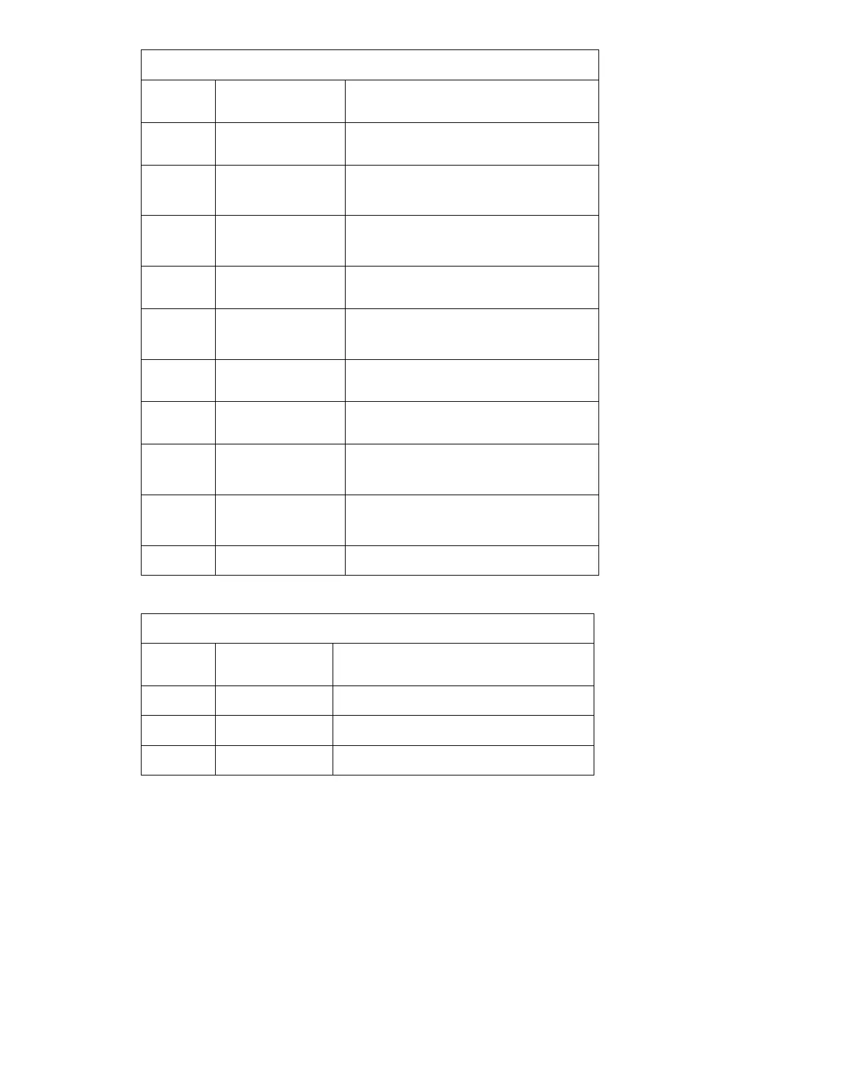
Molex 52207-2490
Pin
Number
Name Description
14 /Power_SW Pull Down Output to Main PCBA Pushbutton –
Power
15 SQRA Digital Output to Main PCBA
Trim knob phase 1
16 SQRB Digital Output to Main PCBA
Trim knob phase 2
17 /Select_SW Pull Down Output to Main PCBA Push-knob –
Trim knob Select
18 CPU_ADC5 Analog Output to Main PCBA
Temperature Sensor
19 /Charge_SW Pull Down Output to Main PCBA Pushbutton –
Charge
20 /Shock_SW Pull Down Output to Main PCBA Pushbutton –
Shock
21 Reserved Reserved for:
Pushbutton – Spare1
22 /Manual_SW Pull Down Output to Main PCBA
Pushbutton – Manual
23, 24 GND System Ground
J317 – RS-232 SERIAL SERVICE INTERFACE
AMP 103673-2
Pin
Number
Name Description
1 Tx RS232 Output
2 Rx RS232 Input
3 GND System / Serial Ground