Section 5: Performance Verification and Safety Testing
2025653-048 Revision B Responder
™
2000 Page 77
Leakage Current
The leakage currents correspond to 110 % of rated voltage for the tested unit. Most Safety Testers take this into account;
otherwise the measured values have to be calculated.
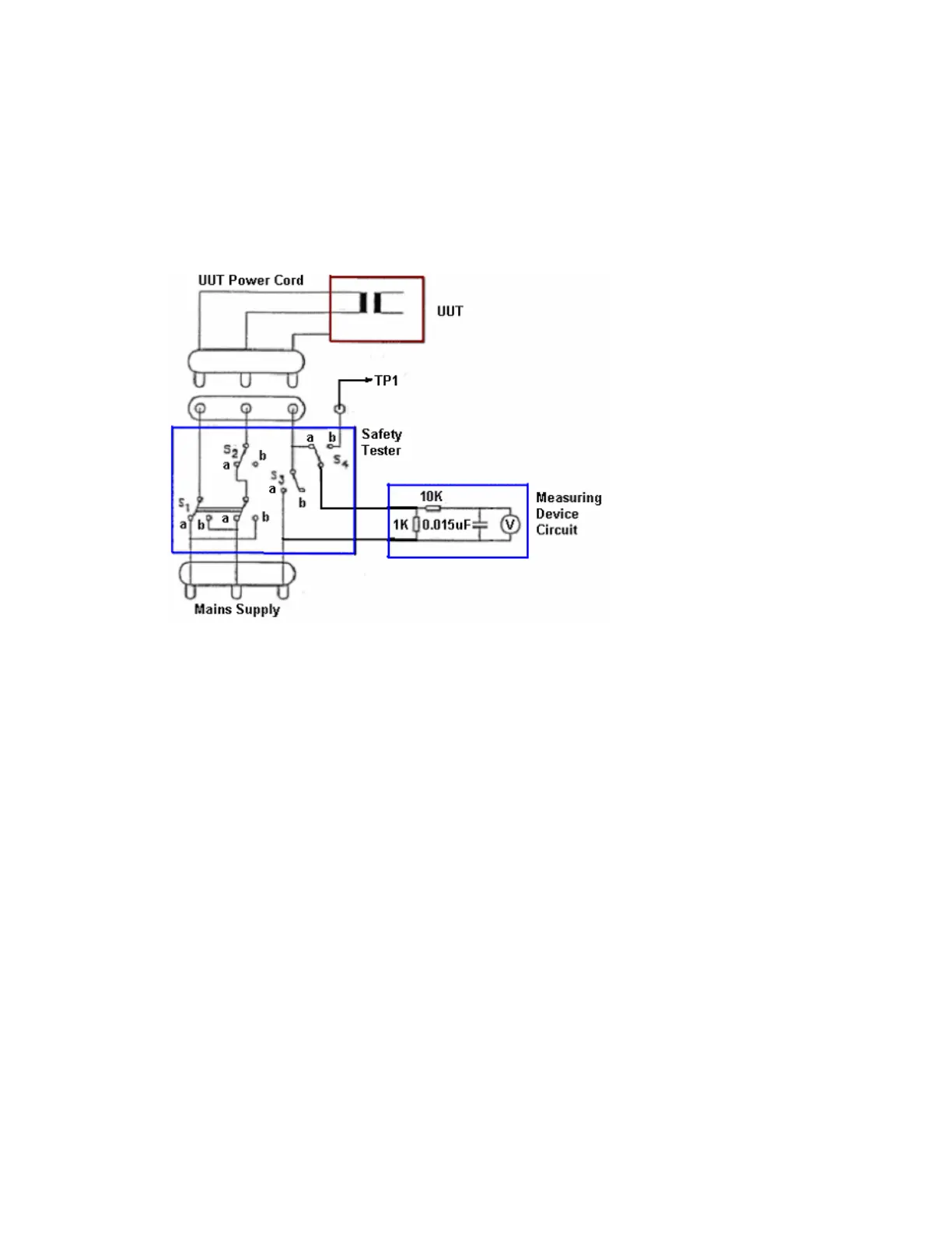
• Use of a “Safety Tester” as show or equivalent test setup (i.e. equivalent test configurations need not
require/use S4).
• Ensure the “Safety Tester” and UUT are configured (if applicable) for the correct voltage.
• Connect the MD (Measuring Device) to the applicable ports on the “Safety Tester” or equivalent test points per
measurement.
• Connect the “Safety Tester” to the mains supply.
• Connect the unit under test to your Safety Tester.
See section 0 for required measuring device circuit and characteristics.
Figure 69: Basic measurement configuration