Section 5: Performance Verification and Safety Testing
2025653-048 Revision B Responder
™
2000 Page 78
Earth leakage (AC Line)
Perform the following tests, with the applicable switch settings on the “Safety Tester” and record the results in the
applicable test form(s).
•
UUT power switch in the “ON” position.
S1: DPDT
Polarity
a) Normal
b) Reverse
S2: SPDT
Neutral
a) Closed
b) Open
S3: SPDT
Ground
a) Closed
b) Open
S4: SPDT
Test point
a) Internal
b) TP1
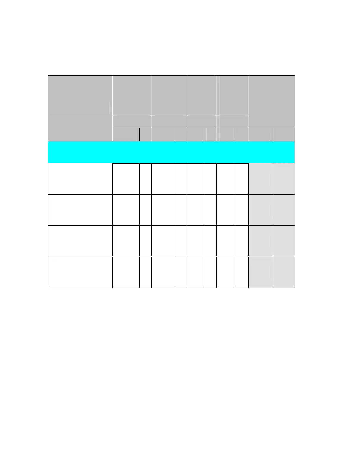
Position Position Position Position
Maximum Limits
(uA)
Test Description
a b a b a b a b EN/IEC UL
Earth leakage current measurements
TP1 – no connection
Polarity: Normal
Neutral: Normal (Closed)
Ground: Open
X X X X
500 300
Polarity: Normal
Neutral: Open
Ground: Open
X X X X
1,000 1,000
Polarity: Reverse
Neutral: Open
Ground: Open
X X X X
1,000 1,000
Polarity: Reverse
Neutral: Normal (Closed)
Ground: Open
X X X X
500 300