SECTION 8: Specifications and Safety
2025653-048 Revision B Responder
™
2000 Page 117
SpO
2
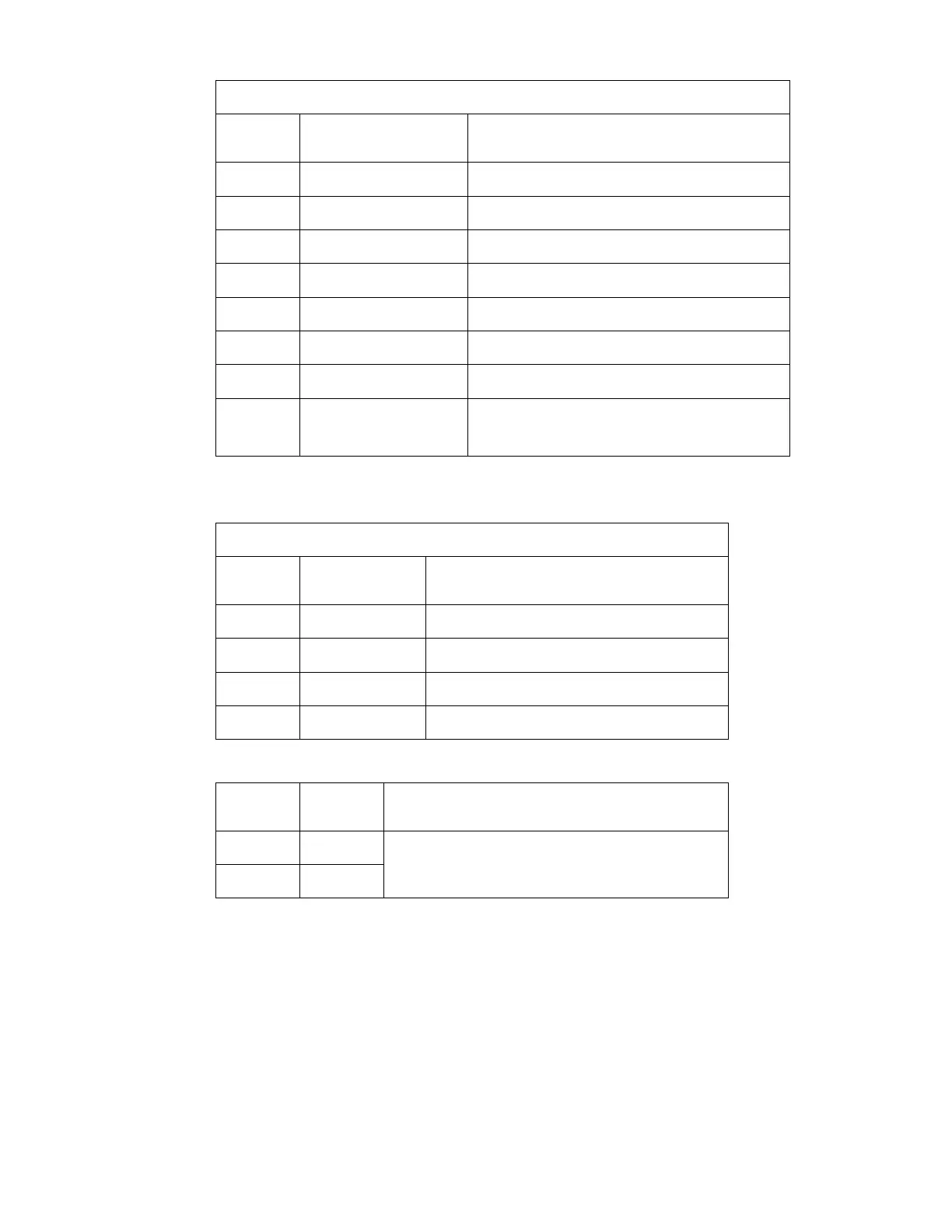
Connector – GE SpO
2
Connector: GE 401762
Pin
Number
Name Description
1 SPO2_RCAL Input – Calibration Data
2 SPO2_LED- Output – Led Neg
3 SPO2_LED+ Output – Led Pos
5 SPO2_ANODE Input – Detector Pos
6 GNDF Isolated Floating Ground
7 SPO2_RCAL_GND Ground – Calibration Data
9 SPO2_CATHODE Input – Detector Neg
4, 8, 10,
11
NC No Connection
Serial Service Connector – DB9-Female
RS232 - DTE. Hardware handshaking not supported.
Connector: Amp 747905-2
Pin
Number
Name Description
2 RS232_RxD Input – RS232 Data
3 RS232_TxD Output – RS232 Data
5 GND Ground
1, 4, 6-9 NC No Connection
Paddle Cradles (Test Load)
Pin
Number
Name Description
RIGHT Apex
LEFT Sternum
A 50Ohm internal defibrillator test load is connected across
the paddle cradles.