SECTION 4: Repair
2025653-048 Revision B Responder
™
2000 Page 47
Rear Cover Installation
Assembly Step Details
If necessary, insert Rubber
Tubing (279 mm ±3 mm 11
in ± 1/8 in) into the groove
on the Front Body.
Note: See Figure 33 for
installation note.
Figure 61: Front Body Tubing Installed
Install Handle to the Rear
Body with two Torx security
screws and two washers.
Figure 62: Handle Installed
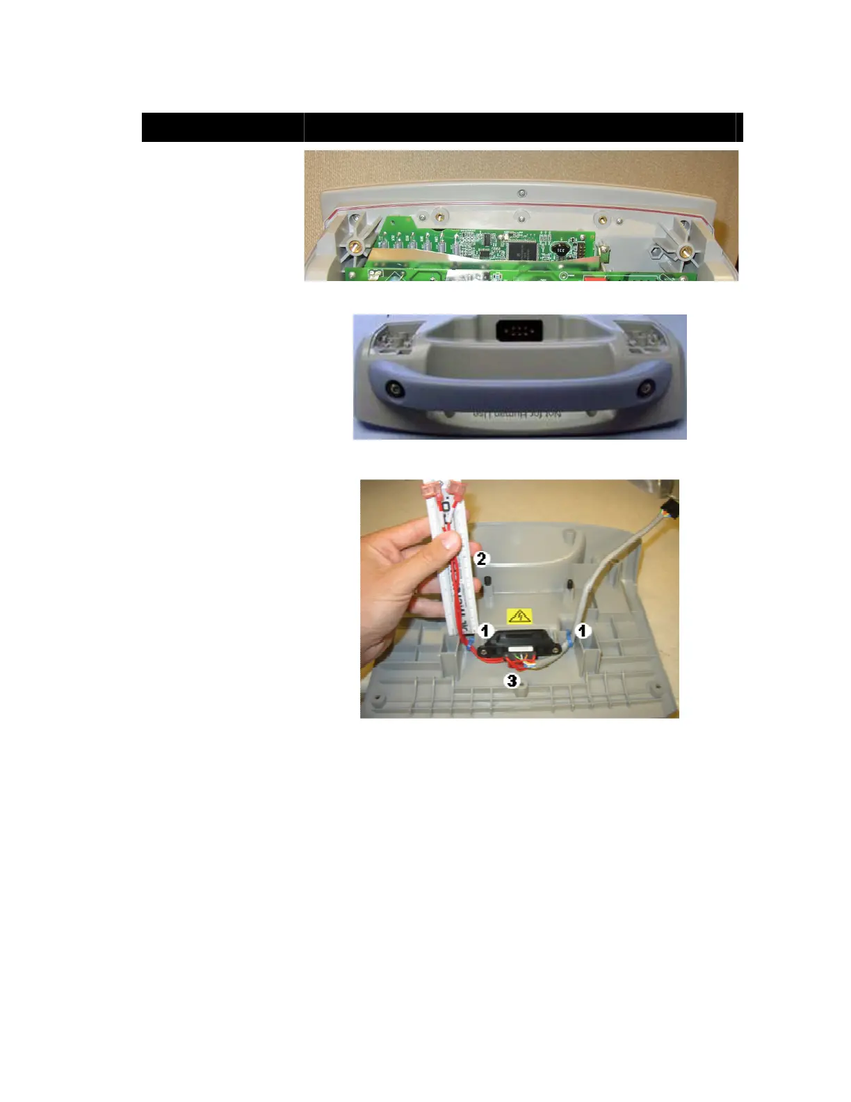
1. Tie cables to Rear
Body.
2. Pull patient cables to a
length of 5.5” to 6”,
measured from the
plastic rib shown to the
top of the plugs.
3. Tuck service loop
under patient
connector.
Figure 63: Rear Cover Cable Installation