SECTION 4: Repair
2025653-048 Revision B Responder
™
2000 Page 48
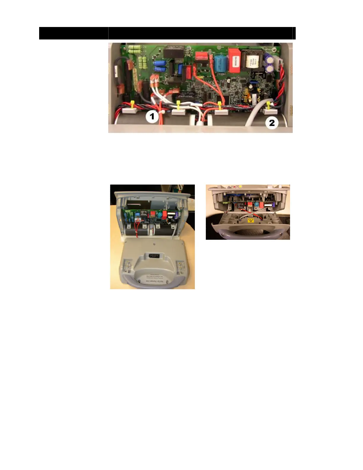
Assembly Step Details
1. Connect P101 (Red
Paddle wire) from
Rear Body to J101 on
the Therapy Board.
Then connect P102 to
J102.
2. Connect gray Paddle
Cable to J109 of
Therapy Board.
Notes: Ensure the wires
are routed exactly as
shown.
The red patient wires
(labeled 1) must go under
the white cap wires. Also,
both plugs of the red patient
connector wires must be
pointing left.
Caution: Equipment
Damage. J122 is not used.
Ensure no cable is
connected to this jack.
Figure 64: Paddle Cables Connected
To attach the Rear Body,
lift the Rear Body and twist
180 degrees
counterclockwise to
assemble into position.
Note: Ensure the red and
gray wire bundles are to
cross as shown.
Figure 65: Rear Body Placement
Figure 66: Rear Body Assembly