SECTION 8: Specifications and Safety
2025653-048 Revision B Responder
™
2000 Page 133
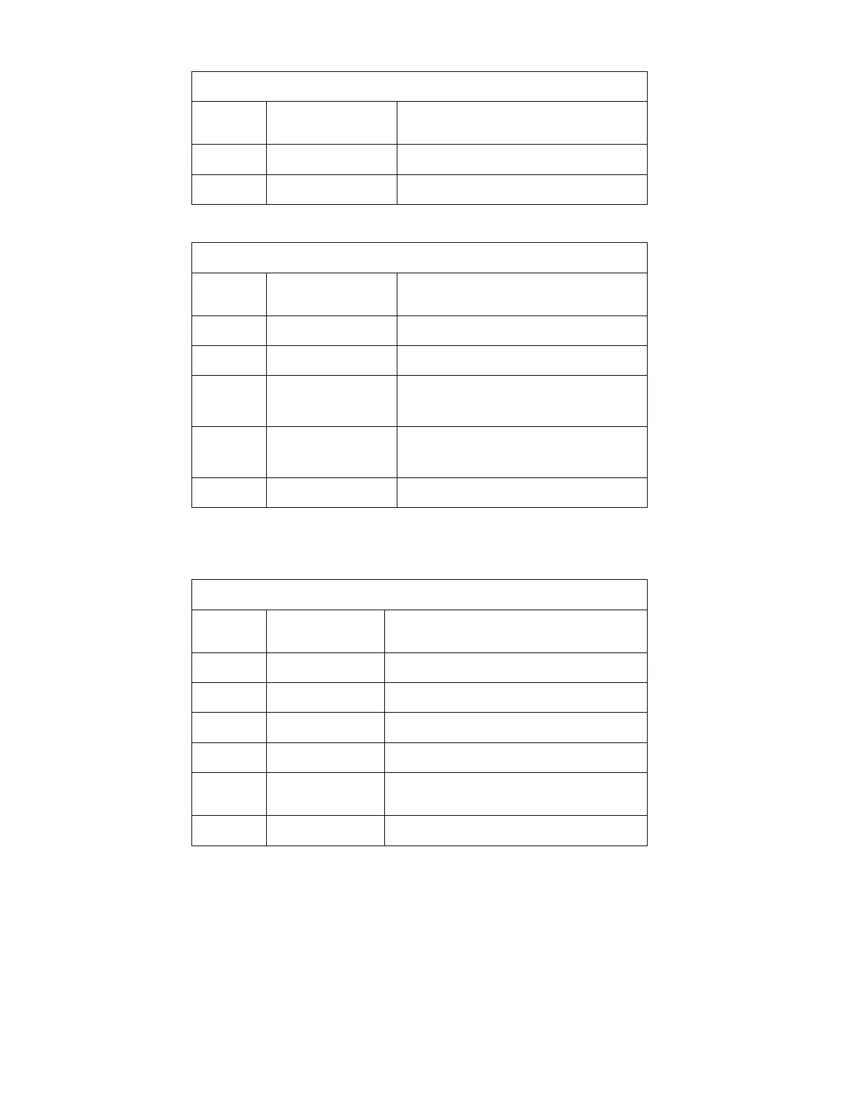
J323 – FAN
AMP 103673-1
Pin
Number
Name Description
1 +12V Power Output
2 /FAN_OUT Pull Down Output – Fan
J324 – ENCODER “Trim Knob”
AMP 0-215079-6
Pin
Number
Name Description
1,2 GND System Ground
3 /Select_SW Pull-down switch input
4 SQRB Digital Input from encoder
Trim knob phase 2
5 SQRA Digital Input from encoder
Trim knob phase 1
6 +5VDC Power Output
SpO
2
PCBA – GE506 Module mounts on the main CPU PCBA with interfacing header connectors plugged directly
together with no cable.
J2 - SpO
2
HOST INTERFACE
Samtec FTSH-107-01-L-D-RA
Pin
Number
Name Description
8 RxD Output – Logic level serial
9 TxD Input – Logic level serial
11 CTS Input – Tied low on Main CPU PCBA
10, 13 +5V 80mA
2, 3, 5, 12,
14
GND Power and Signal Ground Return
1, 4, 6, 7 NC