SECTION 8: Specifications and Safety
2025653-048 Revision B Responder
™
2000 Page 129
6 /ECG_EN ECG Isolated power enable
7 +12V System +12V (nominal)
8 +12V System +12V (nominal)
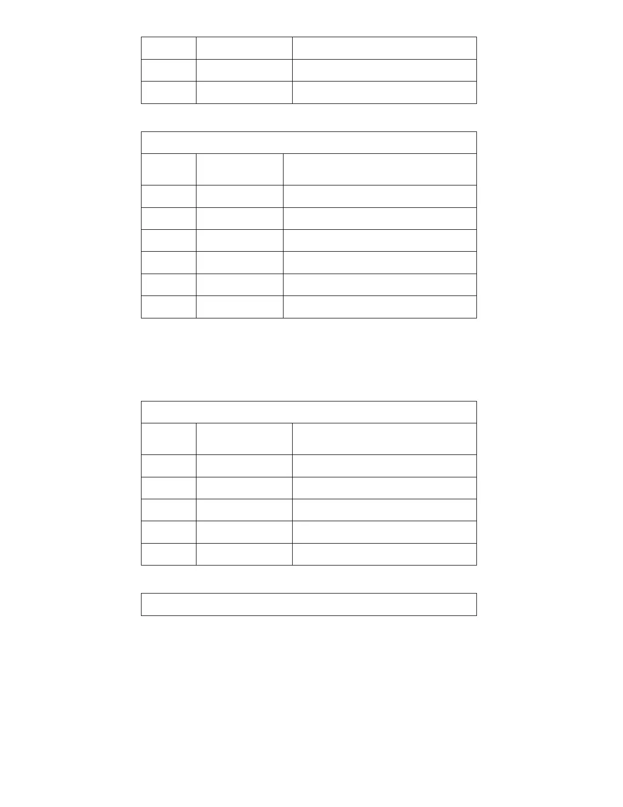
J423 – Patient ECG Connection
Keystone 4903
Pin
Number
Name Description
J4231 RA Electrode - Right Arm
J4232 LA Electrode - Left Arm
J4233 LL Electrode - Left Leg
J4234 V1 Electrode - V1
J4235 RL Electrode - Right Leg
J4236 SHLD Cable Shield
POWER CONTROL PCBA
Responsible for battery charging and DC power switching and distribution. Also includes UI functions
J315 – Power input from DC power supply
Molex 39-30-3058
Pin
Number
Name Description
1 GND System Ground
2 GND System Ground
3 GND System Ground
4 +12V_MAIN Power Input
5 +12V_MAIN Power Input
J325 – Smart Battery Connector – Data and Power
Suyin 250137MR010G101ZU