SECTION 4: Repair
2025653-048 Revision B Responder
™
2000 Page 32
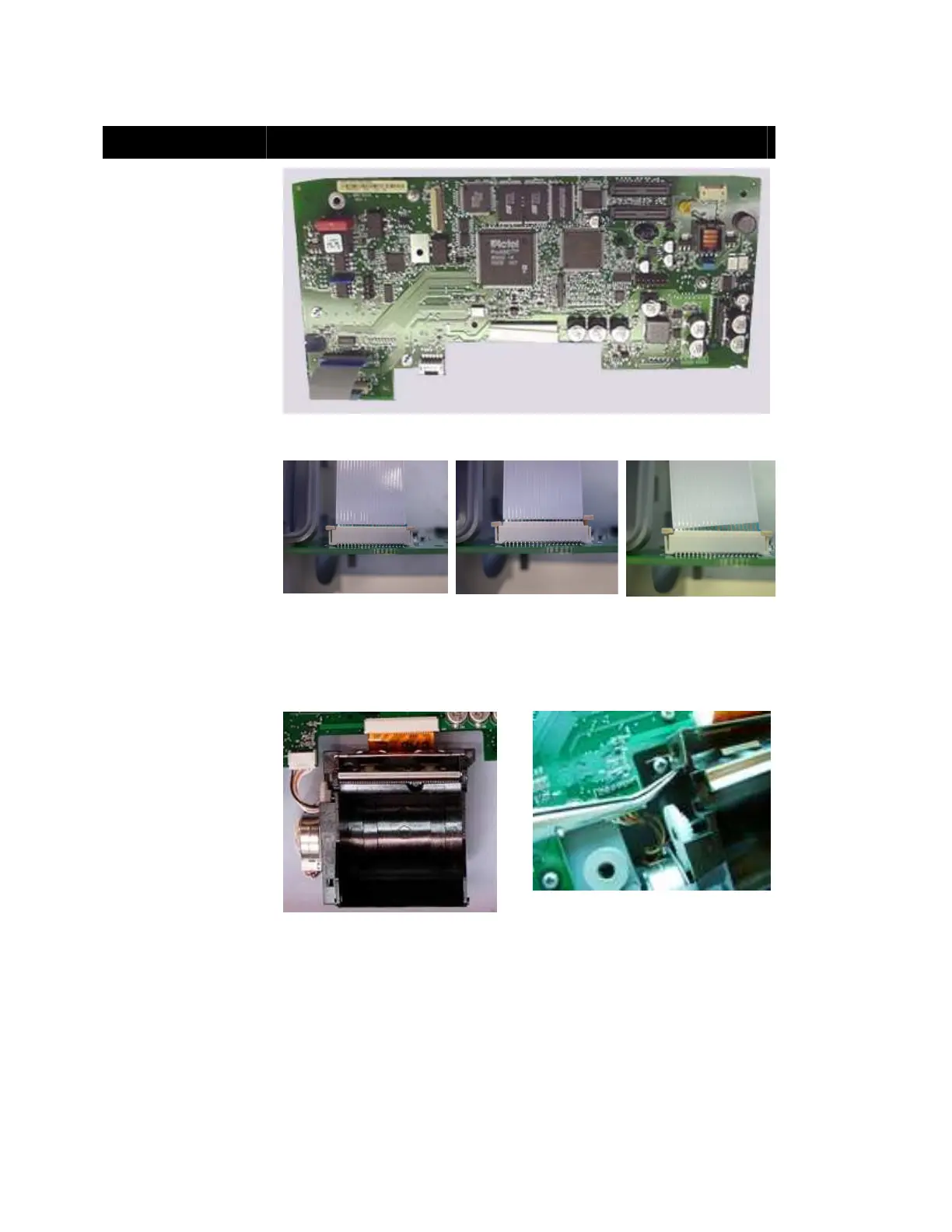
Main Board and Printer Installation
Assembly Step Details
Install Ribbon Cables on
Main Board at J210 and
J218.
Note: Ensure the colored
strip on cable into J218 is
visible when board is
oriented as shown.
Note: Ensure cables are
installed correctly as shown
below.
Figure 5: Main Board
Cable Installation Notes
Figure 6 shows the cable
correctly inserted into the
jack.
Figure 7 shows the jack
latch not fully engaged
(latches on both sides must
be fully depressed).
Figure 8 shows the cable
not fully inserted into the
jack.
Figure 6: Good:
Proper Installation
Figure 7: Bad:
Jack Latch not Fully
Engaged
Figure 8: Bad:
Cable not Fully
Inserted
Note: the following steps detail replacing the entire printer. If the only the printer door is
replaced, see Figure 46 for printer door installation.
Remove the Printer Roller
and connect the printer
cables to J219 and J220.
Note: Ensure the cable and
cable plug are fully inserted
into the cable jacks.
Note: Removing the printer
bracket may help when
connecting the Printer
ribbon cable to the Main
Board.
Figure 9: Printer Connections
Figure 10: Printer Bracket Removal