SECTION 4: Repair
2025653-048 Revision B Responder
™
2000 Page 33
Assembly Step Details
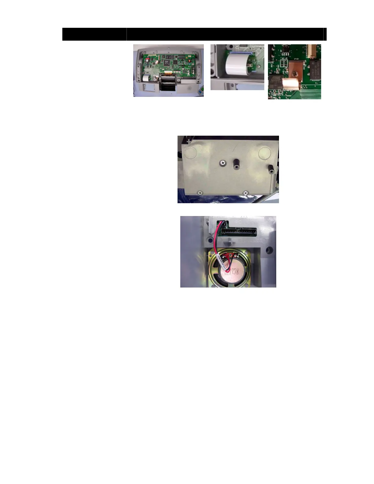
Place the Main Board and
Printer into the Front
Body.
Tuck the ribbon cables
connected to J210 and
J218 as shown.
Secure the Main Board
with seven Philips screws
and install the copper
Contact Spring as shown.
Note: Ensure the printer
ribbon cable does not twist
during installation.
Figure 11: Main Board
Installed
Figure 12: Cable
Detail
Figure 13: Copper
Contact Spring
Installation Detail
Turn the assembly over
(support the Printer so the
cable does not twist) and
secure the printer with three
Phillips screws.
Note: Tighten the center
screw first to properly align
the Printer.
Figure 14: Printer Screws
Connect the speaker cable
to Main Board J216.
Figure 15: Speaker Connection